Horizon UserManualV6.pdf - 第78页
44. Press the System button. 45. Select Change Screen (F2). Adjust Change Screen Board Clamps Set Stop Exit 46. Select Exit (F8). Adjust Change Screen Board Clamps Set Stop Exit 47. Select Exit (F8). Adjust Open Cover Re…
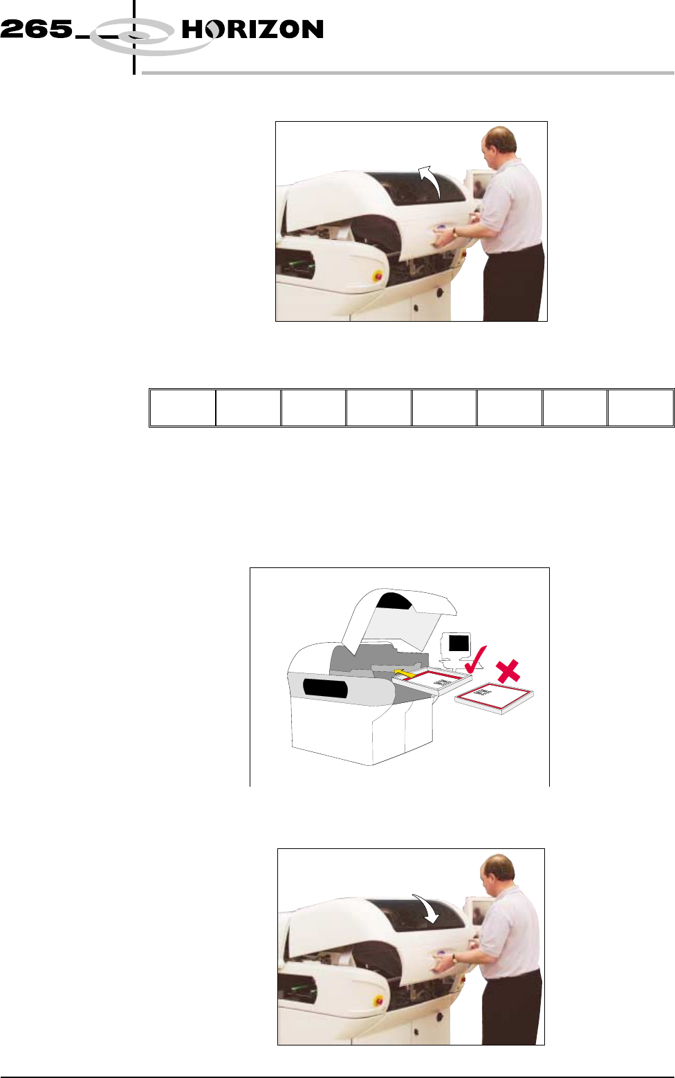
39. Lift the front printhead cover.
40. Select Board Clamps (F3), to open the clamps.
Adjust
Board
Clamps
Set
Stop
Exit
41. Remove the board from the rails.
42. Load the appropriate stencil for the product file loaded, ensuring the correct
orientation of the stencil.
43. Lower the front printhead cover.
Software Version 6 User Manual 1.61
MACHINE PROGRAMMING
STAGE 5D
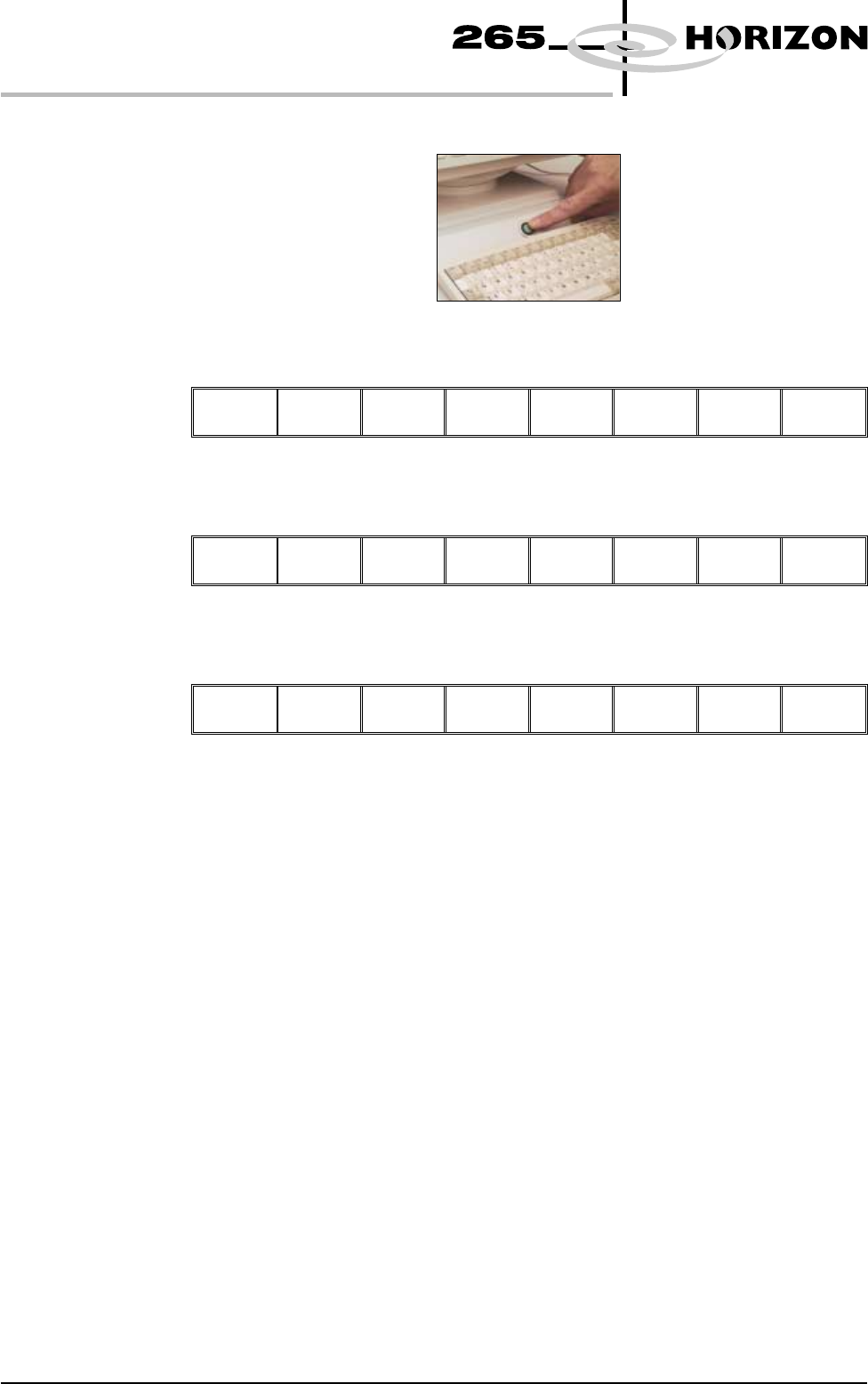
44. Press the System button.
45. Select Change Screen (F2).
Adjust
Change
Screen
Board
Clamps
Set
Stop
Exit
46. Select Exit (F8).
Adjust Change
Screen
Board
Clamps
Set
Stop
Exit
47. Select Exit (F8).
Adjust Open
Cover
Remove
Cleaner
Board
Stop
Full
Width
Load
Width
Print
Height
Exit
48. Go to Stage 6.
1.62 User Manual Software Version 6
MACHINE PROGRAMMING
STAGE 5D
STAGE 5E
Tooling Setup-
AutoFlex
The correct pins for each product are selected automatically when the board size
parameters are programmed into the product file. If the pin configuration needs
to be amended, for example if a support pin coincides with the position of an
underside component and needs to be removed, from the setup page:
CAUTION
BOARD CLAMPS. Care must be taken to ensure that the board clamps
are not damaged when removing or replacing tooling.
1. Select Change Screen (F5).
Mode Load
Data
Edit
Data
Setup
Squeegee
Change
Screen
Change
Tooling
Change
Language
Exit
The message ‘Open Front Cover and Remove Screen’ is displayed.
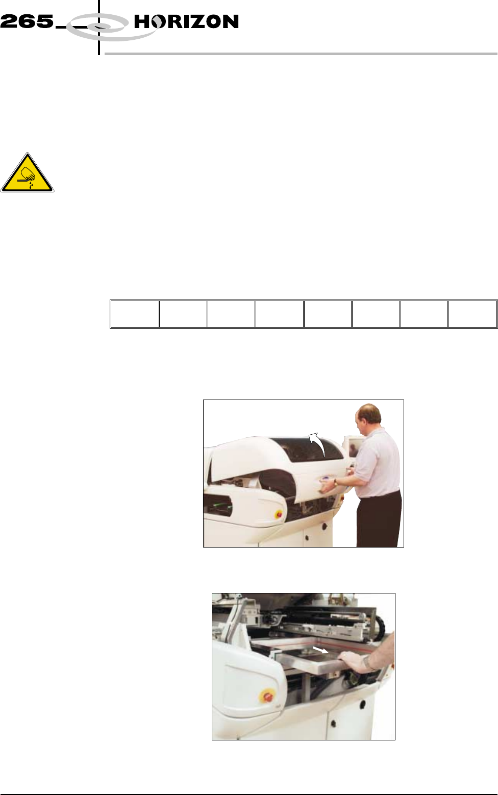
2. Open the front printhead cover.
3. Remove the stencil from the printer.
Software Version 6 User Manual 1.63
MACHINE PROGRAMMING
STAGE 5E
WARNING
BOARD CLAMPS. EXTREME CARE MUST BE EXERCISED WHEN
WORKING IN THE TOOLING AREA OF THE MACHINE TO AVOID
INJURY. THE FOILS ON THE FRONT AND REAR BOARD CLAMPS
ARE VERY SHARP.