444CEMM2(CM201).pdf - 第10页
Page 2-10 444C-E-MMA02-A01-04 Machine Parameter 2-1-12 Network Host name The name used on this mounter and the network of the upper host (PT) to be connected with the mounter . IP address PT is communicated with the moun…
Page 2-9
MACHINE PARAMETER
2
2
2
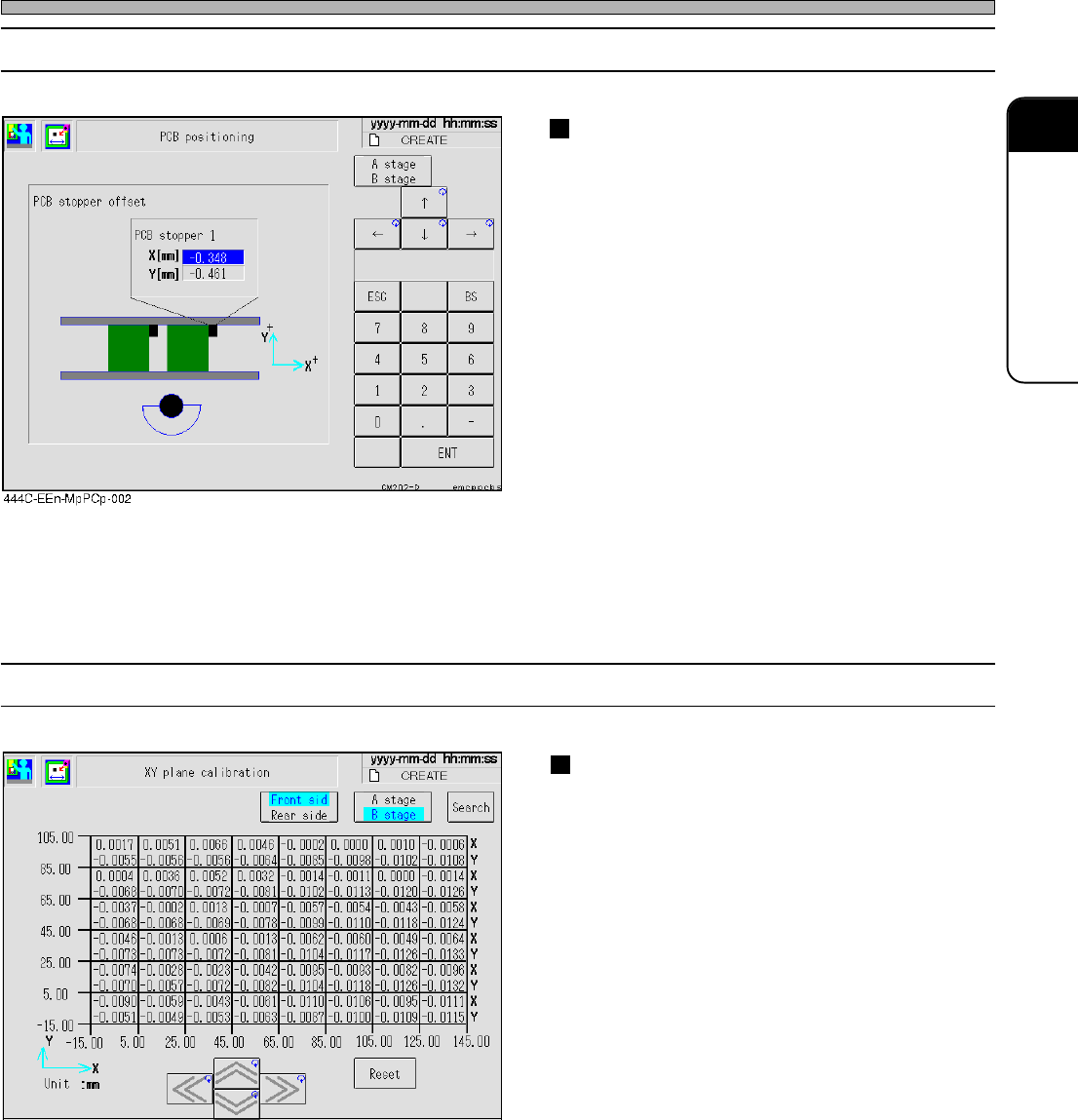
2-1-11 XY Plane Calibration
XY plane calibration
This is the parameter for calibrating the mount-
ing range.
Use this to calibrate the board recognition
position and the mounting position.
Machine Parameter
444C-E-MMA02-A01-05
2-1-10 Board Positioning
Board stopper offset
This displays the position of the board stopper.
Use this for moving to the board recognition
position.
444C-EEn-MpXpc-001
Page 2-10
444C-E-MMA02-A01-04
Machine Parameter
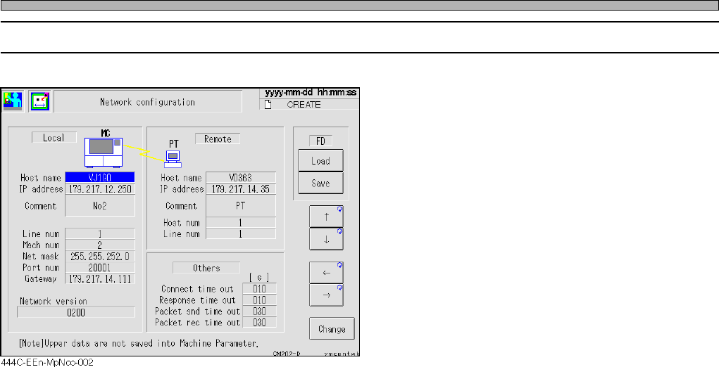
2-1-12 Network
Host name
The name used on this mounter and the
network of the upper host (PT) to be connected
with the mounter.
IP address
PT is communicated with the mounter through
TCP/IP.
“IP address” is the address given to CM201,
CM202, and each mounter separately, to make
the network through TCP/IP.
Host num
The number (01 to FE) given to each upper
host (PT) separately. The mounter always has
“00.”
Line number
The number (01 to FE) particular to the line given to the mounter line which is managed on PT
which is connected with this mounter.
Mach number
The number given to each mounter. This is the individual number (01 to FE) in the same line. The
upper host always has “00.”
Net mask
The mask to be used with the IP address together, to use the network separately.
Port number
The number to determine the type of the network by TCP/IP. As a rule, use number 20001.
Gateway
The IP address of the relay for connecting the PT on other network with this mounter.
Connect time out
The time-out time from the network command by this mounter to be connected to PT.
Response time out
The time-out time from connecting the network to the response returned.
Packet sending time out
The time-out time per packet for sending the file as machine data.
Packet receiving time out
The time-out time per packet for receiving the file as machine data.
∗ Consult with the network manager of the manufacturer for the contents on this screen.
Page 2-11
MACHINE PARAMETER
2
2
2
Machine Parameter
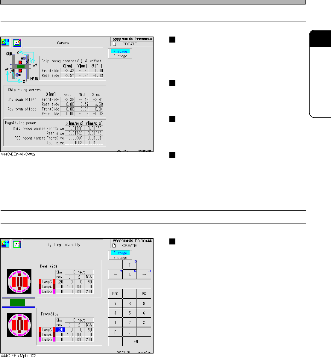
2-1-13 Camera
Chip recognition camera XY
θθ
θθ
θ
offset
This displays the position and inclination of the
chip recognition camera.
Use this for calibrating the chip recognition
position and calculating the chip recognition.
Chip recognition camera magnification
This displays the pixel rate of the chip recogni-
tion camera.
Use this for calculating the chip recognition.
Board recognition camera magnification
This displays the pixel rate of the board
recognition camera.
Use this for calculating the board recognition.
Chip recognition camera reverse scan
offset
This is the offset for the chip recognition
reverse scanning.
Use this for calculating the chip recognition in
the reverse scanning.
2-1-14 Light Quantity
Light quantity offset
This displays the increase and decrease of the
light for each recognition type.
Use this to decide the light quantity for the chip
recognition.
444C-E-MMA02-A01-04