444CEMM2(CM201).pdf - 第98页
Page 3-58 444C-E-MMA03-A04-00 = MEMO =
Page 3-57
SOLUTIONS FOR ERROR
3
3
444C-E-MMA03-A04-00
The Input and Output Check of the Machine
3-5-2 The Output Check after Error
Trouble in the movable section of the machine can be thought as one of the reasons of the errors.
In this section, we describe the way of ensuring that the movable section of the machine related to
the error properly moves or stops.
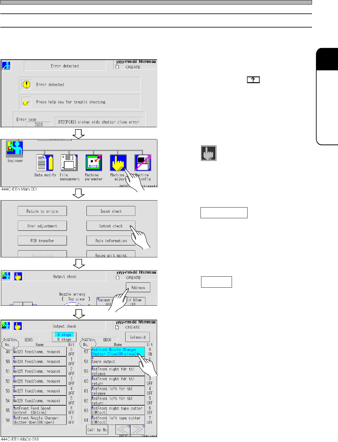
1. Check the error message.
• Check the solutions by of the touch panel
or in the error message list of the Maintenance
Manual.
2. Return to the main menu.
3. Press
Machine
adjust
.
• The machine adjustment screen appears.
4. Press Output check .
• The solenoid screen of the output check is
displayed.
5. Press Address .
• The address screen of the output check
appears.
6. Press the switch which corresponds
to the name of I/O No. described in
the solutions.
• The movable section of the machine moves. If
it does not work (move and stop) properly, it
may have trouble or is disconnected. Inform us
of the exchange.
444C-EEn-MaOc-017
444C-EEn-Ma-002
433C-EOp-Er-002

Page 3-58
444C-E-MMA03-A04-00
= MEMO =
Page 1
A
Action check...................................................1-14
A stage .............................................................1-1
B
B stage.............................................................1-1
BARRIERTA IEL/V .........................................1-18
Belt tension ....................................................1-45
Adjusting the tension ................................1-45
Measuring method....................................1-45
Measuring position ...................................1-45
Board conveyor..............................................1-44
Board positioning .............................................2-9
Board recognition camera XY-axis origin offset ....
2-22
Board recognition camera magnification........2-11
Board stopper offset.........................................2-9
Board transfer belt..........................................1-74
Board transfer roller .......................................1-75
Buzzer ............................................................2-12
C
Camera ..........................................................2-11
Chip recognition camera magnification ..........2-11
Chip recognition camera θ-axis origin offset ..2-24
Chip recognition camera reverse scan offset..
2-11
Chip recognition camera XYθ offset...............2-11
Cleaning the forced-chip-ejecting unit............1-60
Color touch panel ...........................................1-24
Replacing the back light ...........................1-85
Component unit update..................................1-13
Connect time out ............................................2-10
Continuous moving ....................... 1-5, 1-54, 1-58
Conveyor middle position...............................1-47
Conveyor width ................................................2-3
Cutter blade ...................................................1-76
Cutting unit.....................................................1-68
D
Default............................................................2-12
Double tape feeder is installed.......................1-25
F
Fixed blade ....................................................1-70
Fixing groove .................................................1-37
G
Gateway .........................................................2-10
Grease application position............................1-50
Guide shaft.....................................................1-37
H
Heads...............................................................2-3
Head error ........................................................3-6
Head maintenance position ...........................1-61
Heat calibration mark offset .............................2-8
Height teaching jig ...............................2-15, 2-30
History information ...........................................1-4
Host interlock signal output ..............................3-6
Host name......................................................2-10
Host num........................................................2-10
How to check the setting of the blow pressure .....
1-72
I
Indicator .........................................................2-12
IP address ......................................................2-10
J
Judgment value................................................2-4
Bad feeder judgment value for the feeder ..2-4
Bad nozzle judgment value ........................2-4
Recognition error judgment ........................2-4
L
L feder table
in...............................................................1-27
out ............................................................1-26
Light quantity..................................................2-11
Light quantity offset........................................2-11
Line camera ...................................................1-21
Cover glass ..............................................1-21
Line number ...................................................2-10
M
Mach number .................................................2-10
Machine information.......................................1-12
Machine parameter ..........................................2-1
Maintenance motions.......................................1-5
Manual moving.................................................1-5
Mount position........................................ 2-8, 2-34
Mount position offset........................................2-8
Movable blade...................................... 1-70, 1-79
Moving parameter setting ................................2-7
MR unit...........................................................1-20
N
Net mask........................................................2-10
Network..........................................................2-10
NG chip discharge box...................................1-22
Nozzle ............................................................1-28
Cleaning the nozzle..................................1-35
Nozzle reflector ........................................1-29
Nozzle taper face .....................................1-29
Nozzle tip..................................................1-29
Nozzle arrangement.........................................1-5
Checking the nozzle arrangement............1-37
Rechecking the nozzle arrangement........1-41
Nozzle changer ......................................1-30, 2-7
Nozzle changer position offset.........................2-7
Nozzle exchange position ..............................1-31
444C-E-MMA0Z-A01-12