User Manual SIPLACE Head Care Station -.pdf - 第22页
2 Safety 2.7 Safety features 22 User Manual SIPLACE Head Care Station 10/2017 Protective door and safety switch The front protective door can be opened to exchange the placement head and connect the head to the HCS. The …
2 Safety
2.6 Safety instructions for operating the HCS
User Manual SIPLACE Head Care Station 10/2017 21
2.6 Safety instructions for operating the HCS
2.6.1 ESD safety of machine
Please note chapter 2.9 "ESD Guidelines" [}27].
2.7 Safety features
2.7.1 Door and cover
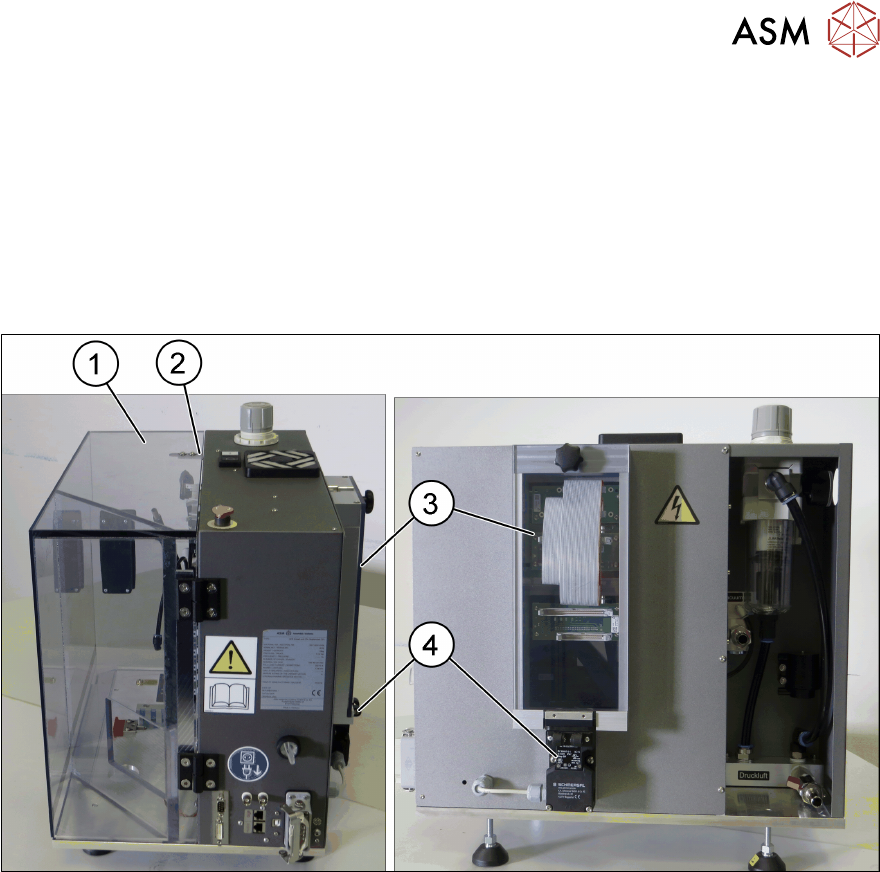
Fig.13: Door and cover
1 Door [03152087-xx] 2 Safety switch of door [03158868-xx]
3 Cover [03110401-xx] 4 Safety switch of cover [03159513-xx]

2 Safety
2.7 Safety features
22 User Manual SIPLACE Head Care Station 10/2017
Protective door and safety switch
The front protective door can be opened to exchange the placement head and connect the head to
the HCS.
The safety switch that is integrated in the head unit ensures that the door is closed and hence pre-
vents unexpected access to the inside of the head unit and interference with the connected parts
during a running verification test. In addition, it locks the door. When the door is locked, the head
verification process can be started.
To lock the door, proceed as follows:
► Install the head. (5.2.1 "Setting up the heads" [}54])
► Initialize the head. (5.2.2 "Switching on the HCS" [}61])
► Close the door.
► Press the Start button. (See item (2) in 2.7.2.1 "Position of switches and buttons on the
HCS" [}23])
If the head verification process has not started yet, you can unlock the door by pressing the Stop
button.
If the head verification process has started, you have the following options to unlock the door:
●
Click the Cancel button in the SIPLACE Test Bench software.
●
Click the Stop button at the HCS.
NOTICE
EMERGENCY OFF button
The EMERGENCY OFF button stops the power supply of 150V to the head unit, unlocks
the door and also immediately aborts all movements.
► Only press the EMERGENCY OFF button in case of an emergency.
► See item (4) in 2.7.2.1 "Position of switches and buttons on the HCS" [}23]
For more information, see 5.2.6.5 "Measurement progress" [}70].
Cover and safety switch
The cover can be removed to connect the flat ribbon cables to the board adapter corresponding to
the placement head that is currently installed on the head unit.
The integrated safety switch ensures that the power supply of 150V is stopped immediately when
the cover is opened.
2 Safety
2.7 Safety features
User Manual SIPLACE Head Care Station 10/2017 23
2.7.2 Switches and buttons on the HCS
2.7.2.1 Position of switches and buttons on the HCS
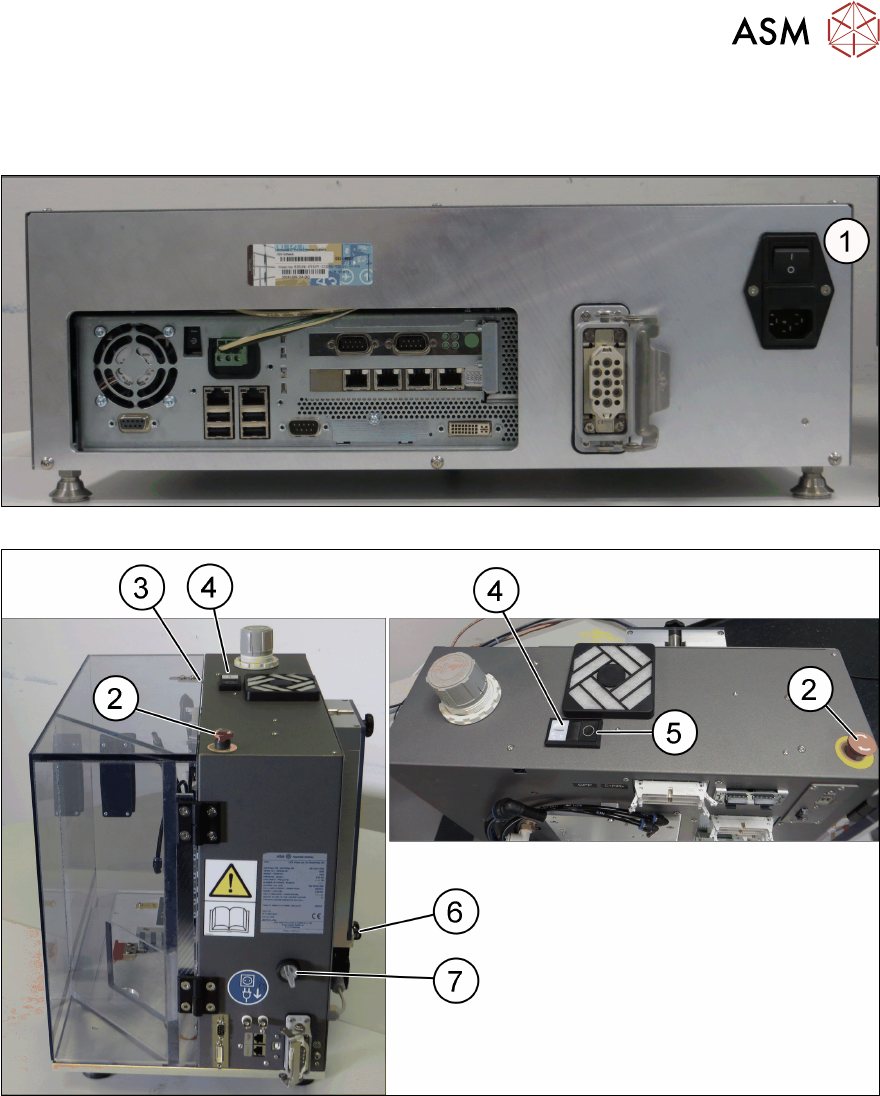
Fig.14: Control box – back side
Fig.15: Head unit - right side / top view
1 Main power switch on control box 2 EMERGENCY OFF button
3 Safety switch of door [03158868-xx] 4 Start button
5 Stop button 6 Safety switch of cover [03159513-xx]
7 HCS power switch