User Manual SIPLACE Head Care Station -.pdf - 第34页
3 HCS description 3.1 Overview of the modules 34 User Manual SIPLACE Head Care Station 10/2017 Head unit – Back side view Fig.21: Head unit – back side view 1 Cover [03089224-xx] with knob 2 Flat ribbon cables 3 Board A…
3 HCS description
3.1 Overview of the modules
User Manual SIPLACE Head Care Station 10/2017 33
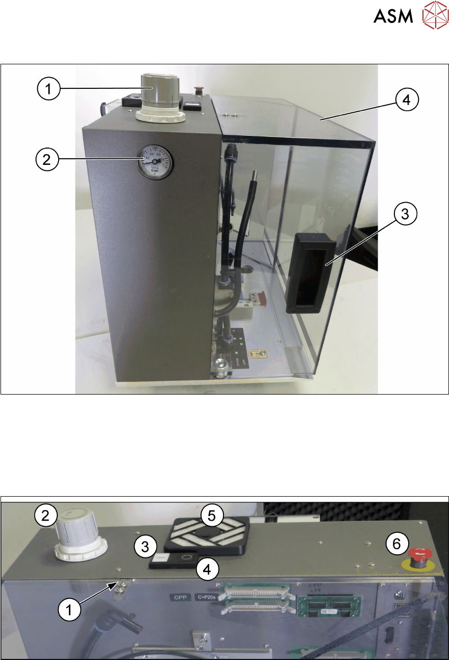
Head unit – Left side view
Fig.19: Head unit – left side view
1 Wheel for compressed air adjustment
[03079075-xx]
2 Manometer [03079075-xx]
3 Door handle [03079084-xx] 4 Door [03156199-xx]
Head unit – Top view
Fig.20: Head unit – top view
1 Safety switch for door [03158868-xx] 2 Wheel for compressed air adjustment
[03079075-xx]
3 Start button [00349458-xx] 4 Stop button [00349458-xx]
5 Filter unit [03003425-xx] 5 EMERGENCY OFF button [03062334-xx]
3 HCS description
3.1 Overview of the modules
34 User Manual SIPLACE Head Care Station 10/2017
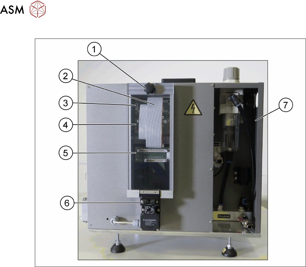
Head unit – Back side view
Fig.21: Head unit – back side view
1 Cover [03089224-xx] with knob 2 Flat ribbon cables
3 Board Adapter-LP C700B-HCSII
[03087842-xx]
4 Board Adapter-LP CPP/CP20-HC-
SII[03087843-xx]
5 Board Adapter-LP DLM4/TWIN-HC-
SII[03087844-xx]
6 Safety switch for cover [03159513-xx]
7 Pneumatic unit [03079075-xx]
3 HCS description
3.1 Overview of the modules
User Manual SIPLACE Head Care Station 10/2017 35
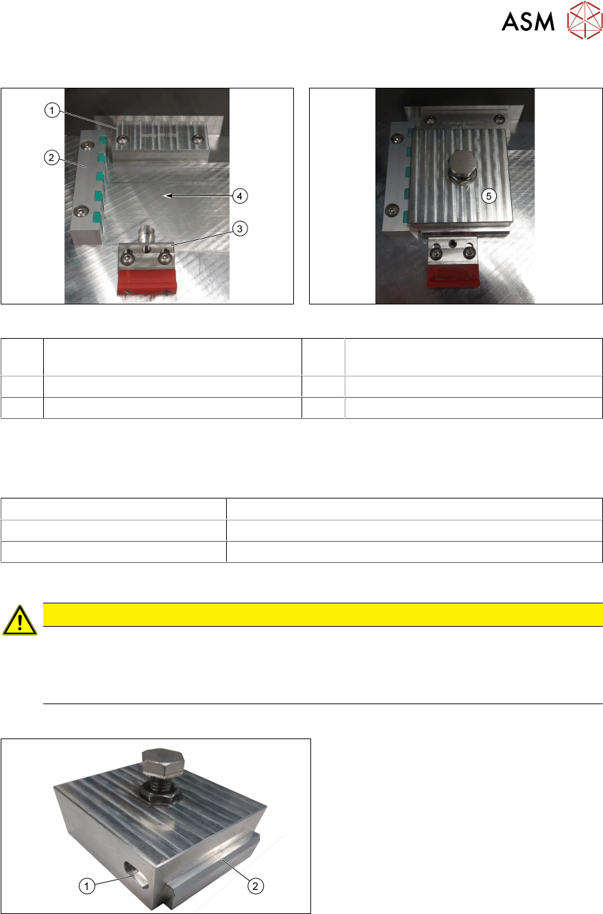
3.1.1.1 Tool area
Fig.22: Tool area without tool Fig.23: Tool area with tool inserted
1 Stopper CP20 - CPP HCSII
[03095249-xx]
2 End stop with sensors for tool identifica-
tion [03085732-xx]
3 Tool clamping [03146437-xx] 4 Place where to insert the tool
5 Inserted tool
Stopper
The stopper aligns the tools to the Z-axis of the head to be verified.
Two stoppers are available and to be used for the respective placement heads:
Stopper Placement head
CP20 – CPP HCSII [03095249-xx] C&P20A, C&P20P, C&P20M, C&P20M2, CPP, CPPM
P+P HCSII [03119655-xx] P&P module
Wrong stopper
CAUTION
Wrong stopper!
A stopper that is not intended for the currently installed placement head could lead to wrong
measurement results during head verification.
► Always ensure to install the correct stopper.
Verification tool
Fig.24: Unit for endurance test HCSII [03086515-xx]
1 Recess for tool identification 2 Edge to mark tool front
For the individual tests of a head verification process, different tools are required.