User Manual SIPLACE Head Care Station -.pdf - 第65页
5 Working with the HCS 5.2 Head verification process User Manual SIPLACE Head Care Station 10/2017 65 Fig.71: TEST: Force sensor reference voltage 20N function ► Click the Test bench service icon (3) . ► Open the Force…
5 Working with the HCS
5.2 Head verification process
64 User Manual SIPLACE Head Care Station 10/2017
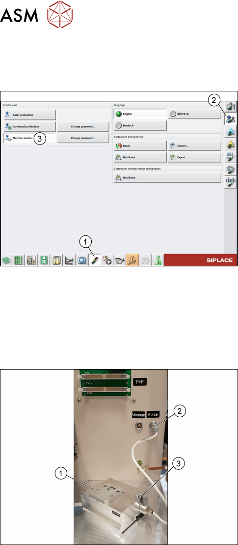
5.2.4 Changing the user role
You are currently logged on as operator. To enable more settings we recommend to switch to
machine service:
Fig.69: Machine service role
► Click the Set settings and options, conveyor
interface, shutdown icon(1).
► Click the Check and set user settings icon(2).
► Select Machine service(3).
ð The user role has been changed to machine
service providing additional functionalities.
5.2.5 Check / adjust the force sensor reference voltage
The force sensor is a shock-sensitive device and easily loses the adjusted reference voltage which
can lead to values not being captured during the measurement.
To avoid the risk of losing values during the force measurement, it is recommended to check the
force sensor beforehand and adjust it if necessary.
Fig.70: Force measurement unit
► Connect the force measurement unit
[03086502](1) to the external Force sensor con-
nector(2).
► Have a watchmakers screw driver within reach
which is compatible with the force sensor
screw(3).
5 Working with the HCS
5.2 Head verification process
User Manual SIPLACE Head Care Station 10/2017 65
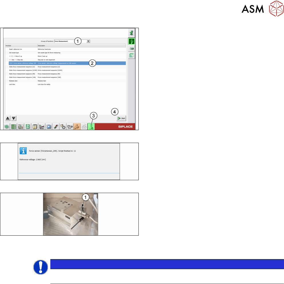
Fig.71: TEST: Force sensor reference voltage 20N function
► Click the Test bench service icon(3).
► Open the Force Measurement menu(1).
► Select the TEST: Force sensor reference
voltage 20N function(2).
► Click the Start button(4).
ð The Reference voltage is displayed and a
countdown during which the force sensor can
be adjusted.
Fig.72: Reference voltage and countdown
► Check the displayed Reference voltage.
Fig.73: Force sensor screw
► Turn the force sensor screw(1) until you reached
a value between +/-10mV.
► If the time has elapsed and the value is still out-
side +/-10mV, click Retry and adjust the force
sensor again.
► Remove the force measurement unit from the
head unit.
► Click the Cancel button.
NOTICE
Adjusting the force sensor is only necessary for the first head verification process.
After that, the adjusted value is saved for all subsequent measurements.
5 Working with the HCS
5.2 Head verification process
66 User Manual SIPLACE Head Care Station 10/2017
5.2.6 Verifying a head
DANGER
EMERGENCY OFF button
The EMERGENCY OFF button immediately aborts all movements and stops the power
supply of 150V to the head unit.
► Press the EMERGENCY OFF button in case of an emergency.
► Click the Test bench inspection icon to start the head verification workflow.
5.2.6.1 Check / enter meta data
► Click the Test bench inspection icon(1).
ð The Meta data tab page is displayed.
Meta data are required to identify the verified head and the person who performed the verification.
All entered data are shown in the protocol that is generated when the head verification is finished.
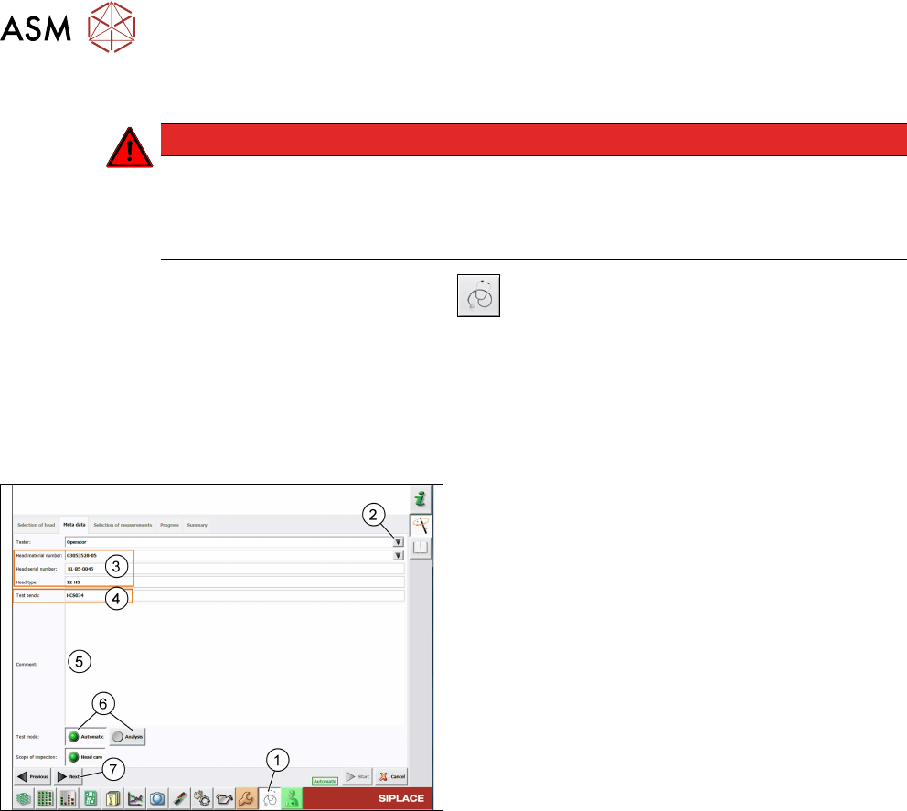
Fig.74: Meta data tab
► The default Tester is set to operator. To change
this, you can overwrite it manually or click the ar-
row(2) to select another tester from a pick list.
For information on how to modify the pick list, see
5.4.1 "Adding users" [}71].
► All head information(3) is read out from the head
EPROM. Verify if the Head material number
corresponds to the information written on the
head label and modify it if applicable.
► The Test bench ID(4) is entered during the in-
stallation of the HCS software. For information on
how to modify this entry, see 5.4.3 "Setting up the
test bench ID" [}72].
► In the Comment field(5), enter a comment if ne-
cessary.
► Select the Test mode(6) to be used:
- Automatic: All tests must be performed.
- Analyze: Individual tests to be performed can be
configured.
► Click Next(7).
See also
2 1.1.2 "Serial number" [}8]