User Manual SIPLACE Head Care Station -.pdf - 第32页
3 HCS description 3.1 Overview of the modules 32 User Manual SIPLACE Head Care Station 10/2017 Head unit – Right side view Fig.18: Head unit – right side view 1 Door [03156199-xx] 2 Start/Stop button [00349458-xx] 3 Whe…
3 HCS description
3.1 Overview of the modules
User Manual SIPLACE Head Care Station 10/2017 31
3.1.1 HCS 2.3 Head Unit CPx + TH [03149140-xx]
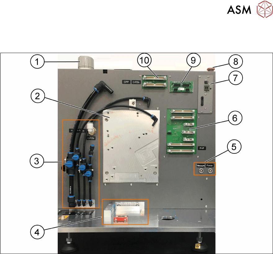
Head unit – Front view
Fig.17: Head unit – front view
1 Wheel for compressed air adjustment
[03079075-xx]
2 Head mounting board [03086172-xx]
3 3.1.6.2 "Pneumatic connections for the
heads" [}41] [03121180-xx]
4 Tool area
5 Electrical connections for external tool
sensors
6 Board adapter head interface C700B for
P&P module [03085198-xx]
7 GigE camera interface [03105372-xx] 8 EMERGENCY OFF button [03062334-
xx]
9 Hotlink camera interface [03008825-xx] 10 Board adapter head interface C700B for
CPP and C&P20x heads [03085198-xx]
3 HCS description
3.1 Overview of the modules
32 User Manual SIPLACE Head Care Station 10/2017
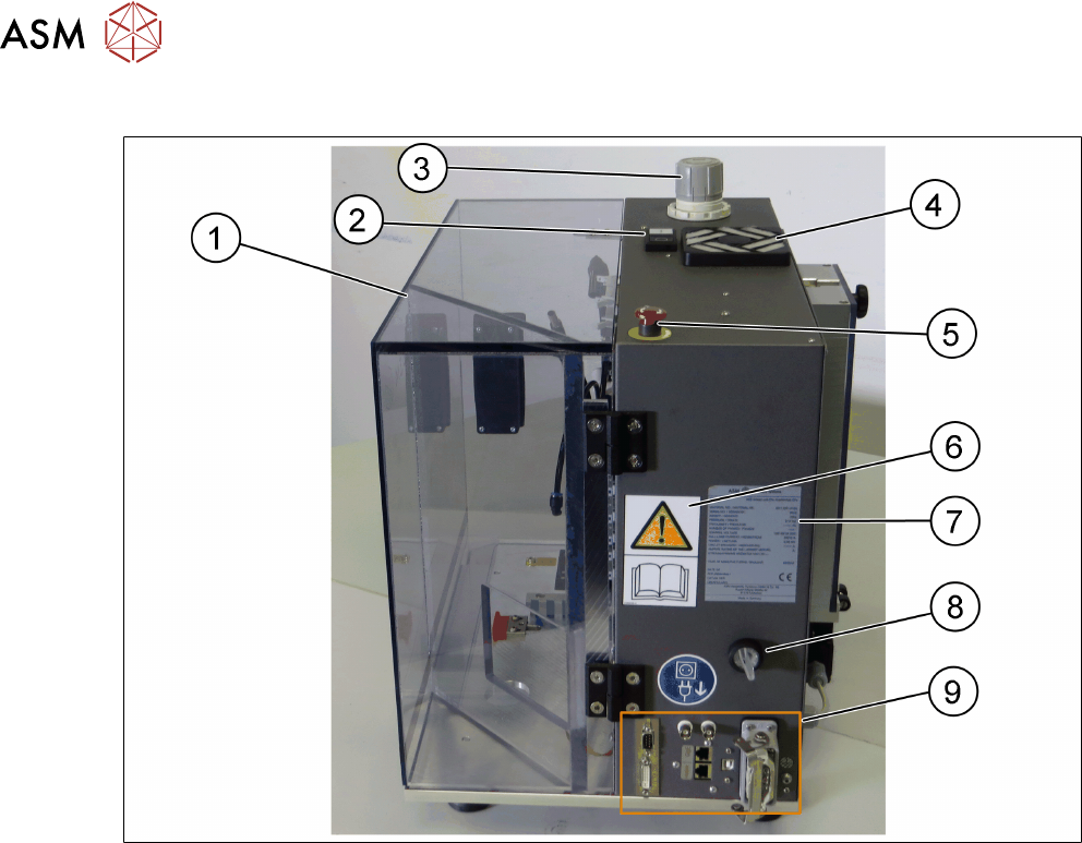
Head unit – Right side view
Fig.18: Head unit – right side view
1 Door [03156199-xx] 2 Start/Stop button [00349458-xx]
3 Wheel for compressed air adjustment
[03079075-xx]
4 Filter unit [03003425-xx]
5 EMERGENCY OFF button
[03062334-xx]
6 W 201 [03009338-xx]
7 Type plate Head Care Station V2.3
[03158942-xx]
8 HCS power switch [03099566-xx]
9 Interfaces for cable connections
3 HCS description
3.1 Overview of the modules
User Manual SIPLACE Head Care Station 10/2017 33
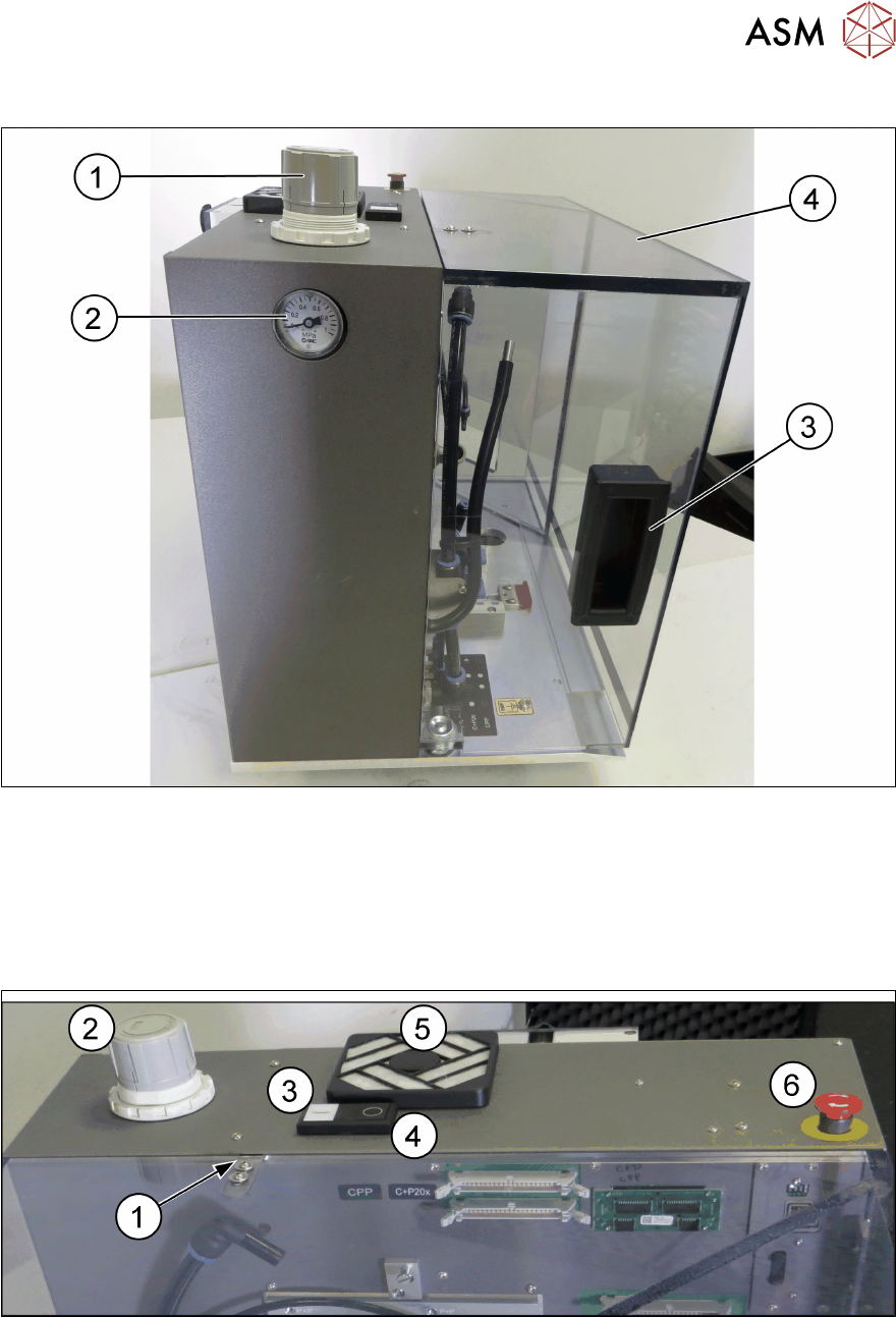
Head unit – Left side view
Fig.19: Head unit – left side view
1 Wheel for compressed air adjustment
[03079075-xx]
2 Manometer [03079075-xx]
3 Door handle [03079084-xx] 4 Door [03156199-xx]
Head unit – Top view
Fig.20: Head unit – top view
1 Safety switch for door [03158868-xx] 2 Wheel for compressed air adjustment
[03079075-xx]
3 Start button [00349458-xx] 4 Stop button [00349458-xx]
5 Filter unit [03003425-xx] 5 EMERGENCY OFF button [03062334-xx]