User Manual SIPLACE Head Care Station -.pdf - 第61页
5 Working with the HCS 5.2 Head verification process User Manual SIPLACE Head Care Station 10/2017 61 Fig.62: Opening the valves ► Open the main valve for the compressed air sup- ply (1) at the back of the head unit. ►…
5 Working with the HCS
5.2 Head verification process
60 User Manual SIPLACE Head Care Station 10/2017
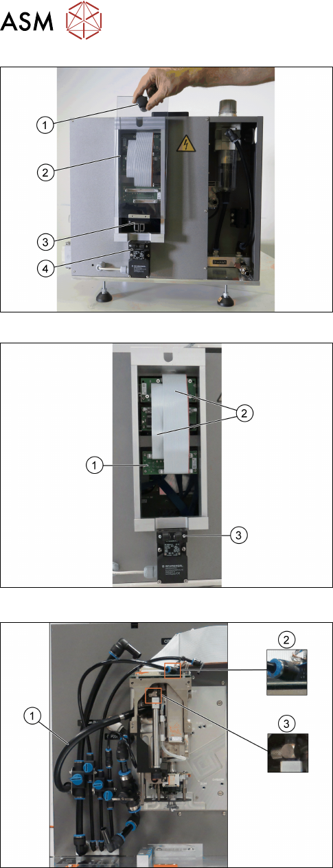
Fig.59: Removing the cover
Connections at the back:
► Grab the knob(1) and pull the protective
cover(2) with the actuator(3) upwards out of the
safety switch(4).
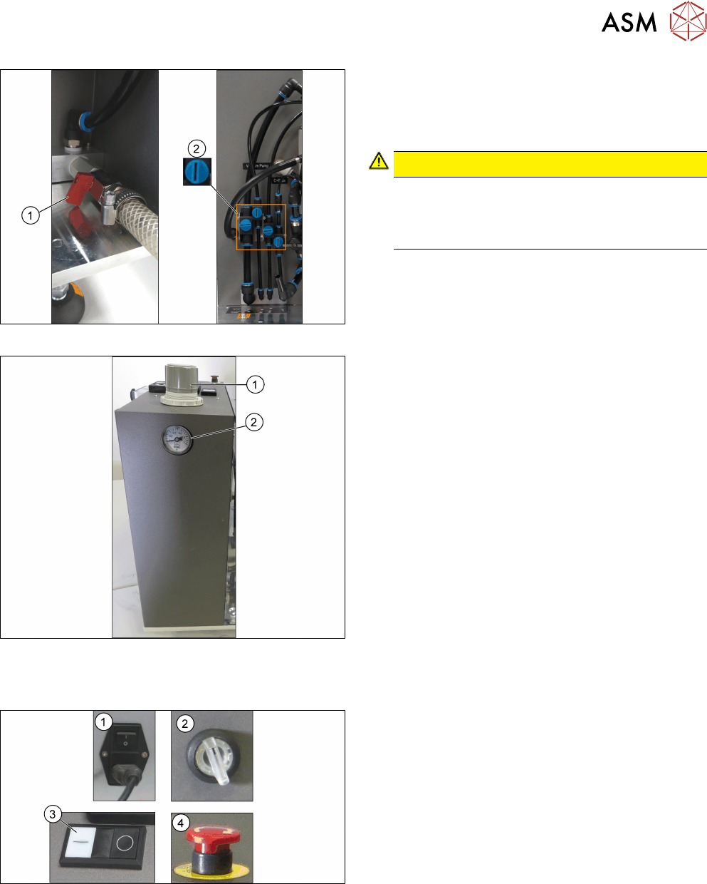
Fig.60: Connecting the flat ribbon cables
► Connect the flat ribbon cables(2) of the Board
Adapter-LP C700B-HCSII[03087842-xx] to the
Board Adapter-LP DLM4/TWIN-HC-
SII[03087844-xx](1).
► Fit the cover back on.
► Make sure that the actuator snaps back into the
safety switch(3).
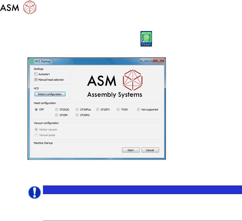
Fig.61: Connecting the hoses
► Connect the hose for the exhaust air to the
head (1).
► Connect the hose for compressed air supply to
the head top(2).
► Connect the hose for compressed air supply to
the pressure regulator valve (PRV)(3).
For information on the correct pneumatic connections,
see 3.1.6.2 "Pneumatic connections for the
heads" [}41].
5 Working with the HCS
5.2 Head verification process
User Manual SIPLACE Head Care Station 10/2017 61
Fig.62: Opening the valves
► Open the main valve for the compressed air sup-
ply(1) at the back of the head unit.
► Open the respective valves(2) for the com-
pressed air supply to the head.
CAUTION!
Risk of injury due to loose pneumatic hoses!
Always ensure the valves of the pneumatic con-
nections for the heads are closed before switch-
ing on the main valve for compressed air.
.
For information on the correct pneumatic connections,
see 3.1.6.2 "Pneumatic connections for the
heads" [}41].
Fig.63: Adjustment wheel and manometer
► Pull off the cap(1) of the adjustment wheel.
► Turn the adjustment wheel until the mano-
meter(2) shows 4.8 bar.
5.2.2 Switching on the HCS
Fig.64: HCS switches and buttons
► Switch on the main switch(1) on the control box.
► Switch on the HCS power switch(2) on the right
side of the head unit to power on the head unit.
► Ensure that the EMERGENCY OFF button(4) is
released.
► Press the Start button(3) on top of the head unit.
► Wait until the head is initialized.
ð Green LEDs at the intermediate distributor
board light up and for C&P heads, the LEDs
at the DPs flash when the head is initialized.
5 Working with the HCS
5.2 Head verification process
62 User Manual SIPLACE Head Care Station 10/2017
5.2.3 Starting the HCS software
► On the desktop, double-click the TB Start icon to start the verification software:
ð The HCS Startup screen is displayed:
Fig.65: HCS Startup screen
If the head was initialized correctly, the head is automatically detected and selected under Head-
configuration.
NOTICE
No head detected
If the head initialization failed, no head can be detected. Manual head selection is selec-
ted
under Settings. Not supported is selected under Head configuration.
Autostart option
If the Autostart option is enabled, the software starts automatically within seconds. See 5.2.3.1
"Test Bench Start screen" [}63].
Manual head selection
If the Manual head selection option is enabled, heads need to be selected manually before start-
ing the SIPLACE Test Bench.