AppX.A_spec_mx3600_sys_10.11.pdf - 第13页
MX - 3600 / CXI3600M X / Specification confidential 13 / 39 spec_mx3600_sys_10.11.doc 2.2.5. Image Geomet ry & Resolution The MX - 3600 Image Geom etry (Magnification) can be contin uously programm ed between 15.0 m …

MX-3600 / CXI3600MX / Specification
confidential 12/39 spec_mx3600_sys_10.11.doc
2.2.4. Detector Setup / MX-3600
The MX-3600 is configured with a high resolution image intensifier and a high
resolution digital camera. This detector setup is fully compatible to the X2
configuration, which provides a maximum on application compatibility
between the X2 and the CXI-MX-3600.
Image Intensifier Specification
The E58xx series from Toshiba is graded up to the new CsI direct deposit
technology in conjunction with current technologies of thick input screen with
a very fine pillar shape structure and a thin output screen on a single thick
glass output window with an anti-reflecting coating.
Image Intensifier Specification MX-IID4/2
Image Intensifier Type Dual 3/2 inch II (J-Advanced Technology)
X-Ray Characteristic Easier penetration of soft X-Rays
Resolution High Resolution Setup/ 77/110 lp/cm
Entrance Field Size N-Mode: 75 +/-5mm (3 inch)
M-Mode: 50 +/- 5mm (2 inch)
Output Diameter 20 +/- 1mm
Digital Camera Specification
Digital monochrome camera link camera with 12 bit greylevels/pixel.
Camera Specification MX-DCL1k
Dig.Camera Spec.
X2-Setup
Output Diameter
20 +/- 1mm
Camera type
HR monochrome camera / high sensitive
2/3 inch progressive scan
Pixel-area
1360 x 1024
active area: 1028 x 1028
Max. framerate
20 fps
> 4 fps
Data Depth
10 bit
10 bit
Interface
Camera link
Camera Link
MX-3600 / CXI3600MX / Specification
confidential 13/39 spec_mx3600_sys_10.11.doc
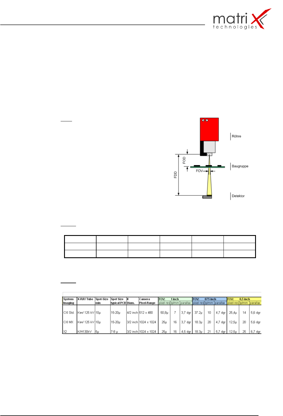
2.2.5. Image Geometry & Resolution
The MX-3600 Image Geometry (Magnification) can be continuously
programmed between 15.0 mm to 26.5 mm Field of View Size (FOV) by
changing FOD (Focus to Object Distance).
This is realised in the MX-3600 by the programmable z-axis motion for the X-
RAY tube.
Fig.8: Image Geometrie
FOD Focus to Object Distance
FDD Focus to Detector Distance
FOV Field of View
Table 1: Max. FOV-Geometries
FOV (mm)
FOD (mm)
FDD (mm)
Mag.
lp/mm
µm/Pixel
25,5
200
400
2
16
25
12,5
66,7
266,7
4
>20
12,5
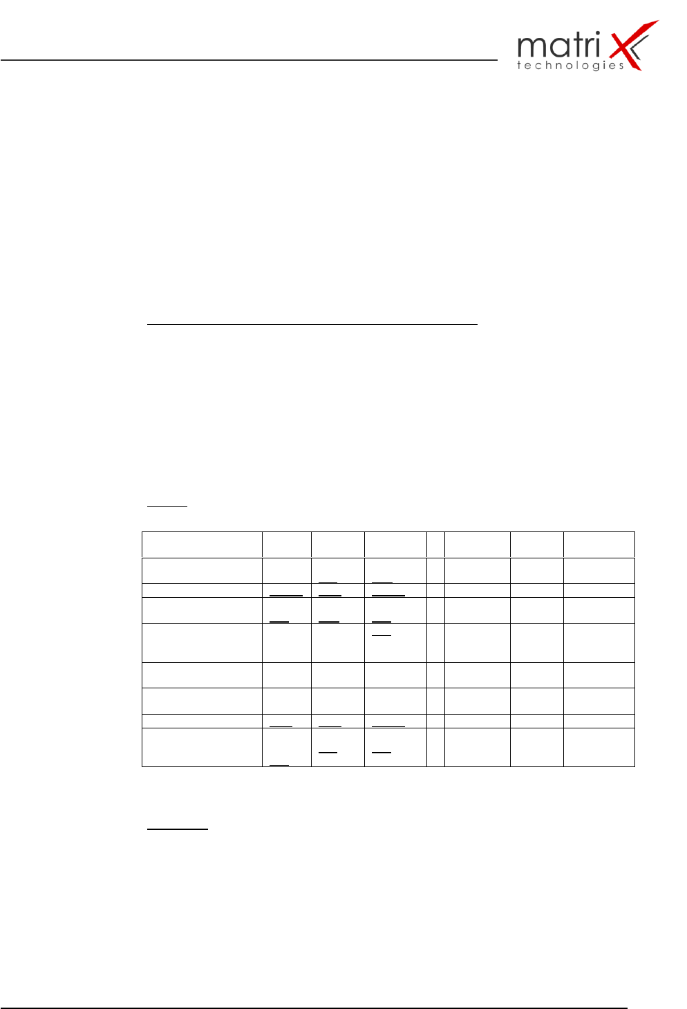
Table 2: Typical FOV Setup for SMT applications
The comparison to the CXI systems displays the advantages in respect of
resolution and FOV-size of the CXI (MX) and X2 systems versus the old
CXI3600 standard setup.
MX-3600 / CXI3600MX / Specification
confidential 14/39 spec_mx3600_sys_10.11.doc
2.3. Motion System
2.3.1. Load/Unload Handling
The load/unload section is designed for high speed throughput. For faster load
and unload cycles a board buffering in the input and output conveyor is used.
During the inspection and load/unload cycle the X-Ray power is permanently
one, which is saving x-ray ramp-up and down cycles. Via timer the X-Ray
switches in stand-by mode, if no sample board is loaded.
Status definitions in the MX-3600 load/unload system:
IC Status/Input - Conveyor
XY-T Input Conveyor to Table
OC Status/Output-Conveyor
Table 3: Summary of all process-steps for load/unload of inspection sample:
Load/Unload Step
IC
XY-T
OC
X-RAY
SMEM
A
Inspection
Unload Board from
XY-T to OC
loaded
Load to
free
free to
load
Beam-On
Ready
No
Move XY-T to IC
loaded
Free
loaded
Beam-On
Busy
No
Load Board from IC
to XY-T
load to
free
free to
load
load to
free
Beam-On
Busy
No
XY-T inspection
move
free to
load
loaded
free
Beam-On
Stop
Active
Auto Beam-Off
Cycle
IC
XY-T
OC
X-RAY
SMEM
A
Inspection
Unload Board from
XY-T to OC
free
Load to
Free
Free to
load
Beam-On
Stop
No
Move XY-T to IC
Free
Free
loaded
Beam-On
Stop
No
Load Board from IC
to
XY-T
Free
to
free
Free to
free
Load to
free
Beam-Off
Ready
No
Optional:
Dual Board Load:
two boards are loaded on-to the x/y table to run inspection mode
together !
dual load board size: 2 x (200mm x 305mm) or (8’’ x 12’’)
time saving effect: approx. 3-4s per board!
(close to half loading cycle / 1 loading cycle = 8s)