AppX.A_spec_mx3600_sys_10.11.pdf - 第18页
MX - 3600 / CXI3600M X / Specification confidential 18 / 39 spec_mx3600_sys_10.11.doc 2.3.3. Z - Axis The z-drive is hoste d t ogether with the X -ray tube in the ex tra shi elded x - ray tube cham ber. The z-axis is exa…
MX-3600 / CXI3600MX / Specification
confidential 17/39 spec_mx3600_sys_10.11.doc
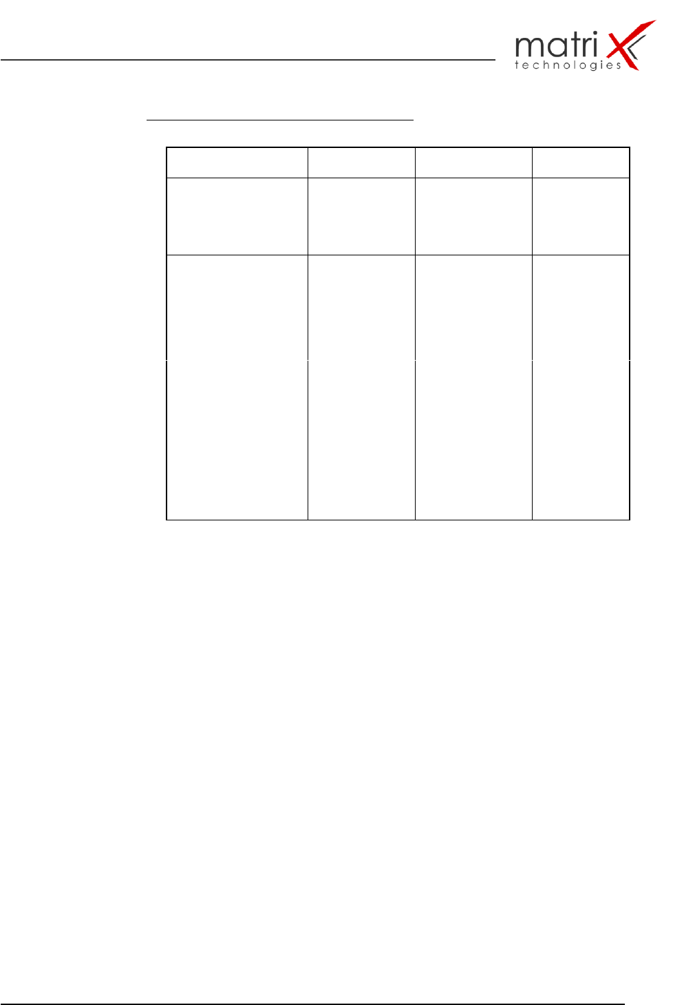
Table 5: MX-3600 / Key-specification items / X-Y table:
Parameter
X-Axis
Y-Axis
Comment
Drive System
prec. Servo –
spindle drive
prec. Servo-
spindle drives
Controller
digital servo
digital servo
amplifiers
Interface
CAN
CAN
Driving Distance
500mm
(20’’)
350mm
(14’’)
Velocity (max)
Up to 500mm/s
Up to 500mm/s
Position Accuracy
Up to 25 µm
Up to 25 µm
Position Repeatability
+/- 25 µm
+/- 25 µm
Total Accuracy
+/- 50 µm
+/- 50 µm
( 20 mm FOV)
Typ. FOV Positioning
Time
<200ms
<200ms
typ. FOV = 25mm
(1inch)
Max. Sample Load
up to 2,5 kg
up to 2,5kg
Board Clamping
side-clamp
side-clamp
pneumatic
Max. Board Thickness
up to 4mm
up to 4mm
Operating Temperature
15-35 dgr C
15-35 dgr C
MX-3600 / CXI3600MX / Specification
confidential 18/39 spec_mx3600_sys_10.11.doc
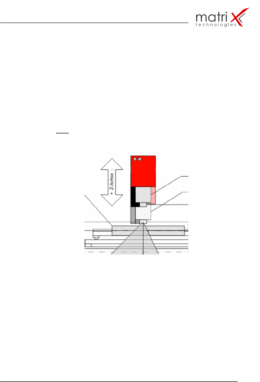
2.3.3. Z - Axis
The z-drive is hosted together with the X-ray tube in the extra shielded x-ray
tube chamber.
The z-axis is exactly vertically configured against the x-y base and equipped
with a programmable servo motor to provide a continuously changeable field
of view.
z-axis directions 0…165mm/6.5’’ drive distance/cont.
Fig.10: z-axis with x-ray tube motion

MX-3600 / CXI3600MX / Specification
confidential 19/39 spec_mx3600_sys_10.11.doc
2.4. Control Computer System
2.4.1. Control Computer
The VME Computer Unit is fully replaced by a high-speed PC with the
following key parameters:
PC basic configuration:
Processor: ≥ Dual Core High Power Processors
> 3,5 GHz with 2MBL2Cache
Memory: ≥ 4 GByte SDRAM
Hard Drive : > 40 GByte
Optical Drive: DVD ROM / 8x IDE Drive
Framegrabber: High-Speed Framegrabber (12/16Bit)
2.4.2. System-Software
Windows XP Professional License ( or W2003 Server)
Halcon Image Library License (incl. Hardware-Key)
Optional: Data Base Client License (customer specific setup)
2.5. System Interface & Barcode Scanning System
2.5.1. Inspection System Barcode Handling
The Standard Barcode Setup includes:
Conveyor Mounting Kit : top and bottom
Power connection point at input conveyor site
RS-232 Interface connection point at input conveyor site
1D and 2D barcode capability
Optional:
Belt-Conveyor System (600-800mm)
incl. Autowidth-Adjust
2.5.2. SMEMA Interface
SMEMA electrical Interface
SMEMA PCB transportation height