AppX.A_spec_mx3600_sys_10.11.pdf - 第34页
MX - 3600 / CXI3600M X / Specification confidential 34 / 39 spec_mx3600_sys_10.11.doc 5.2. MX - 3600 geometrical calibration & test (FOV & Flatness Test) FOV-T est The MX3600 has a variable X -RAY source (z1 axis…
MX-3600 / CXI3600MX / Specification
confidential 33/39 spec_mx3600_sys_10.11.doc
5. System Calibration & Diagnostics
5.1. MX-3600 / grey-level consistency and repeatability test and
calibration (Gamma-Test)
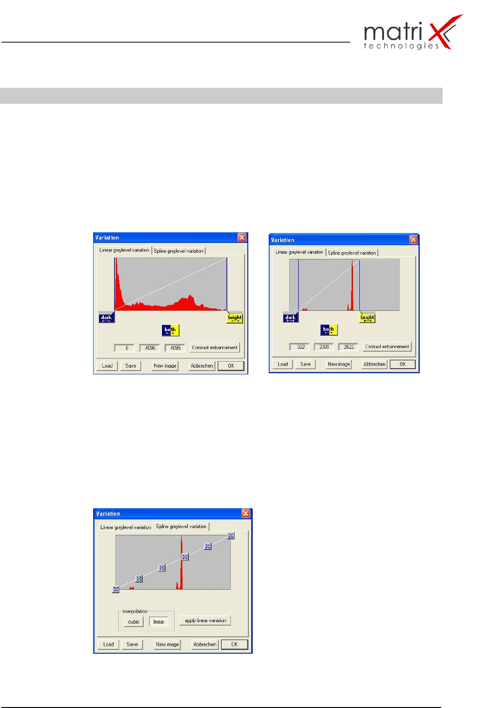
The calibration tool provides the possibility to optimize and select the grey-level
function for the specific application range. i.ex.: SMT Solder-joint inspection or
back-end chip inspection,….
Fig. 20.a: Full 4096 (8/12 Bit) Greylevel Range b: specific grey-level range
The X2/MX-3600 calibration plate guarantees the test and calibration of a pre-
defined repeatable grey-level function curve over the full 12 Bit (0…4096) range.
Image calibration and correction is achieved by applying a gain and offset to each
pixel using the equation:
c[m,n] = gain[m,n] *b[m,n] + offset[m,n]; where b is the raw input image and c is
the corrected image.
Fig. 21: min. 4 testpoints (testplates) for gamma-curve calibration
MX-3600 / CXI3600MX / Specification
confidential 34/39 spec_mx3600_sys_10.11.doc
5.2. MX-3600 geometrical calibration & test (FOV & Flatness
Test)
FOV-Test
The MX3600 has a variable X-RAY source (z1 axis) (SOD) and a fixed object to
detector distance. The key part of the geometrical test and calibration procedure
is the FOV calibration. The FOV adjustment is related to the z1 (x-ray source)
axis calibration (SOD) and the detector z2 position (ODD).
Assuming ‘z1’ equals the SOD and ‘z2’ equals the ODD, then ‘z1 + z2’ equals the
SDD and the geometric magnification ‘M’ is given by:
M = (z1 + z2) / z1;
Assuming that ‘dsize’ equals the size of the projected image on the detector, than
for a given FOV size ‘fobj’ at the object plane:
dsize = fobj * M = fobj * (z1 + z2) / z1;
System
Camera
FOV:
1 inch
FOV:
075 inch
FOV:
0,5 inch
Imaging
Pixel-Range
pixel-
res.
lp/mm
parallax
pixel-
res.
lp/mm
parallax
pixel-
res.
lp/mm
parallax
CXI Std.
512 x 480
50,8µ
7
3,7 dgr
37.2µ
10
4,7 dgr
25,4µ
14
5,6 dgr
CXI MX
1024 x 1024
25µ
16
3,7 dgr
18.3µ
20
4,7 dgr
12,5µ
20
5,6 dgr
X2
1024 x 1024
25µ
16
4,5 dgr
18.3µ
21
5,7 dgr
12,5µ
25
6,7 dgr
Table 9: FOV setup for typical FOV’s
Additional Calibration Parameters:
Image Flatness
Image Focus-Centering
5.3. MX-3600 / X-RAY Image Resolution Test
(Line-pair Gauge Test)
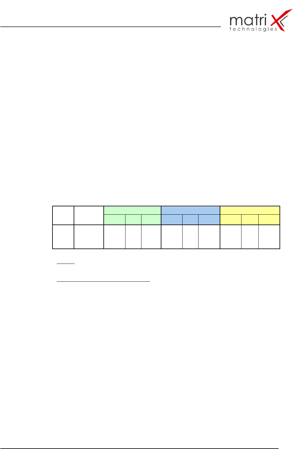
The calibration board includes a line pair gauge test field to be used for the
resolution test. The resolution is measured according international standards: in
lp/mm (line-pair mm) the specification numbers are displayed in the FOV/Imaging
specification (refer to table 8).The following resolution test examples describe the
different stages of the resolution test.
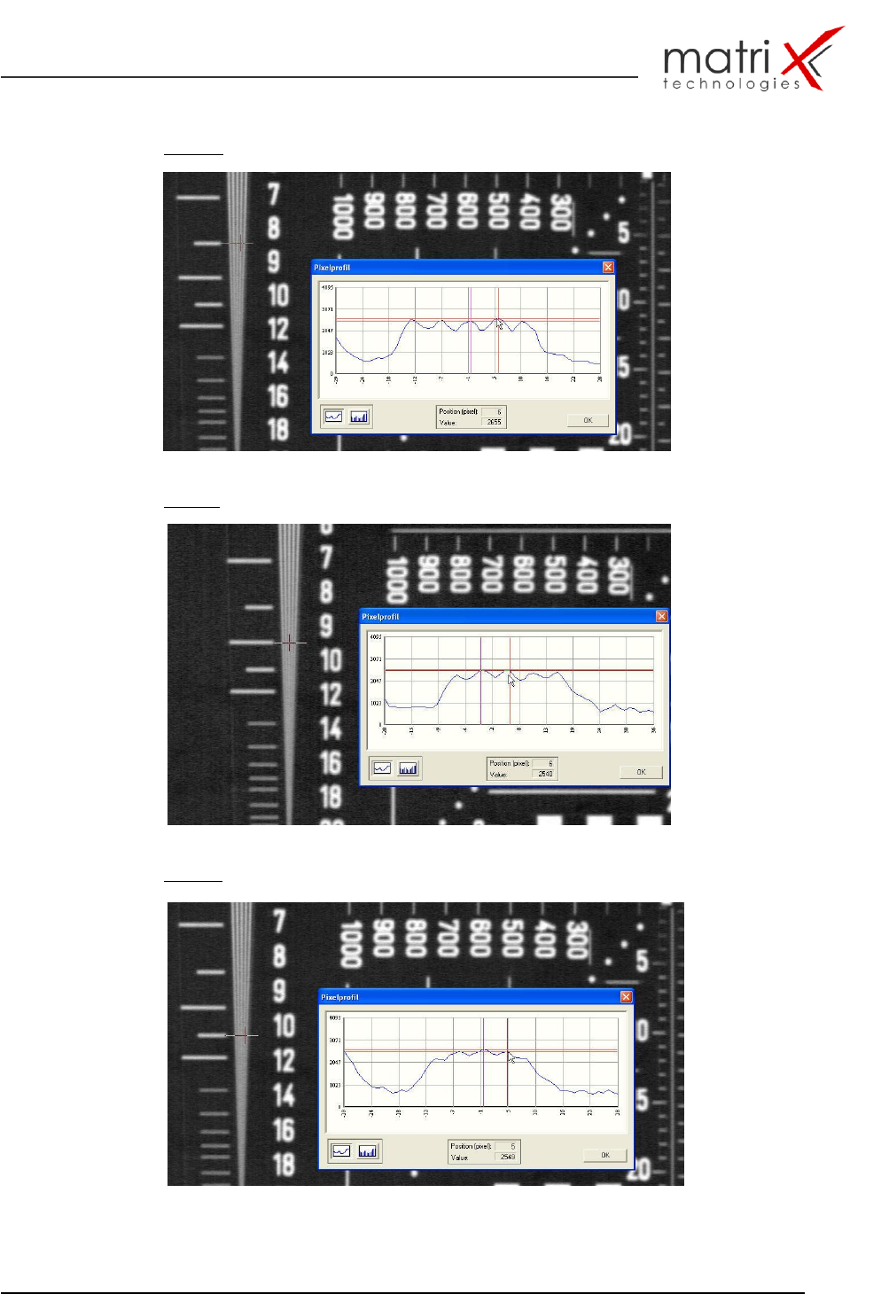
Pict 19.b shows the max. acceptable spatial resolution: 9lp/mm – Pict.19.c
(10lp/mm) is out of the spatial resolution criteria.
The MX-3600 has automatic test capability for this resolution test - the
justification criteria’s for the lp/mm threshold are defined in the CTF XRAY
criteria’s for spatial resolution.
MX-3600 / CXI3600MX / Specification
confidential 35/39 spec_mx3600_sys_10.11.doc
Fig. 22a: 8 lp/mm with perfect shape and clear differentiation
Fig. 22b: 9 lp/mm with acceptable shape and clear differentiation
Fig. 22c: 10 lp/mm with non-acceptable shape and unclear differentiation