AppX.A_spec_mx3600_sys_10.11.pdf - 第30页
MX - 3600 / CXI3600M X / Specification confidential 30 / 39 spec_mx3600_sys_10.11.doc 4.2. MIPS_Inspect / X-RAY Solder Joint Inspection Algorithm Library (MIPS_SJ- L) The core of the inspec tion process is the alg orithm…
MX-3600 / CXI3600MX / Specification
confidential 29/39 spec_mx3600_sys_10.11.doc
4. MX-3600 / Application Features
4.1. Fiducial Test (Pass Marking Test)
The fiducial test should run before starting inspection of a new PCB sample or
any other sample what has potential fiducial points on it. The fiducial test can
correct the following in-tolerances in the inspection process:
Sample board is not (unparallel,..) in correct loading position
Sample board is slightly bent during clamping
Board warpage, which effects the x-y positions
Board outside dimensions are slightly off as result of an intolerant de-
panelisation process
The following fiducial types can be used:
Layout printed fiducials (dark contrast check) – soldered or unsoldered
like cross points, double cross points, circle, ring, squares, …!
Layout based drilled hole fiducials – like drilling holes and vias.
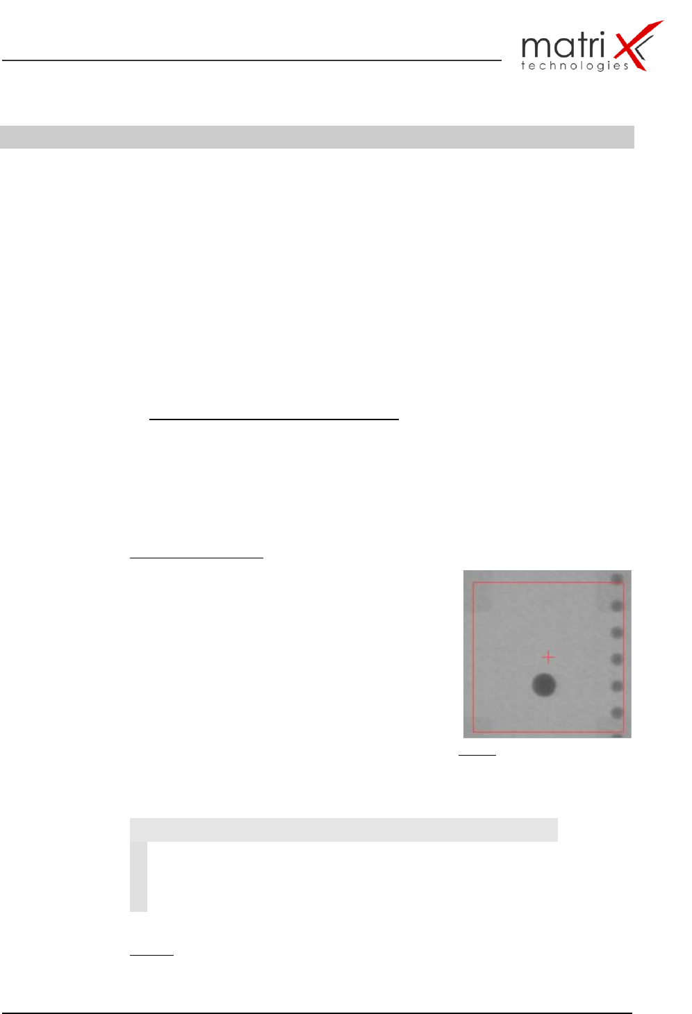
Fiducial test principle:
The fiducial test is correcting the off-positions from
the ideal CAD position coordinates by searching in
a predefined search window the specified fiducial-
pattern (in the example fig. 16 a dark circle) – after
locating the fiducial the object will be centred.
This procedure needs to be done at least at one
more fiducial ideally 3 or 4 fiducials. The detected
centre point coordinates are then processed and
corrected against the machine based cad point
position. The results of the fiducial calculation
process are shown in table 8.
Fig. 16: Fiducial object with search
window and cad point (red cross)
Fiducial test result to be used for X-Y CAD position correction:
Table 8: fiducial test result data
Fiducial Test
1
DeltaX
Corrected Fid. Cad X-Position
2
DeltaY
Corrected Fid. Cad Y-Position
3
FiducialError
= 0 Fid.-object successfully located
= 1 no Fid. Object detected or
multiple objects detected
MX-3600 / CXI3600MX / Specification
confidential 30/39 spec_mx3600_sys_10.11.doc
4.2. MIPS_Inspect / X-RAY Solder Joint Inspection Algorithm
Library (MIPS_SJ-L)
The core of the inspection process is the algorithm library for solder joints and
components.
A detailed description and specification of the algorithm are documented in:
SMT/THT X-RAY Inspection algorithm specification
MX3600-Algorithm Manual
An overview about the inspection capabilities and the defect classes is
documented in:
AppendiX: F Solder joint inspection & component defect library
(attached to this document!)
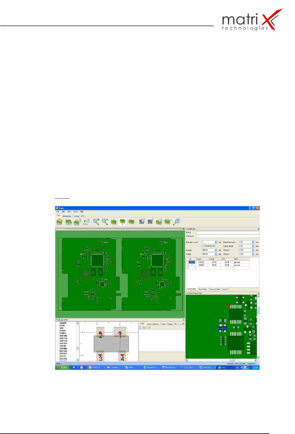
The classification techniques for the defect detection are shown in
Fig. 17: Inspection program generation with Gencad Cad Import
MX-3600 / CXI3600MX / Specification
confidential 31/39 spec_mx3600_sys_10.11.doc
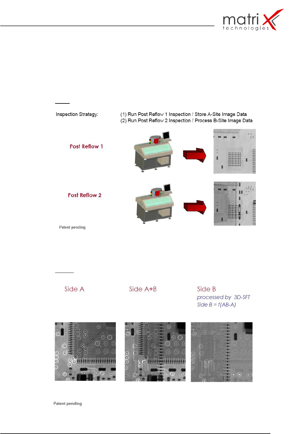
4.3. Slice-Filter Technique (SFT™)
The new (3D) Slice-Filter Technique provides the capability for double-sided
PCB-assembly inspection of 2 x Reflow processed boards.
Fig.18: SFT Principle
Fig. 19a: Processed Slice-Filter Example