AppX.A_spec_mx3600_sys_10.11.pdf - 第29页
MX - 3600 / CXI3600M X / Specification confidential 29 / 39 spec_mx3600_sys_10.11.doc 4. MX -3600 / Application Featu res 4.1. Fiducial Test (Pass Marking Test) The fiducial test sho uld run before s tarting inspection o…
MX-3600 / CXI3600MX / Specification
confidential 28/39 spec_mx3600_sys_10.11.doc
3.5. X-SPC / real Time Process Control Software
MX / real-time SPC functions
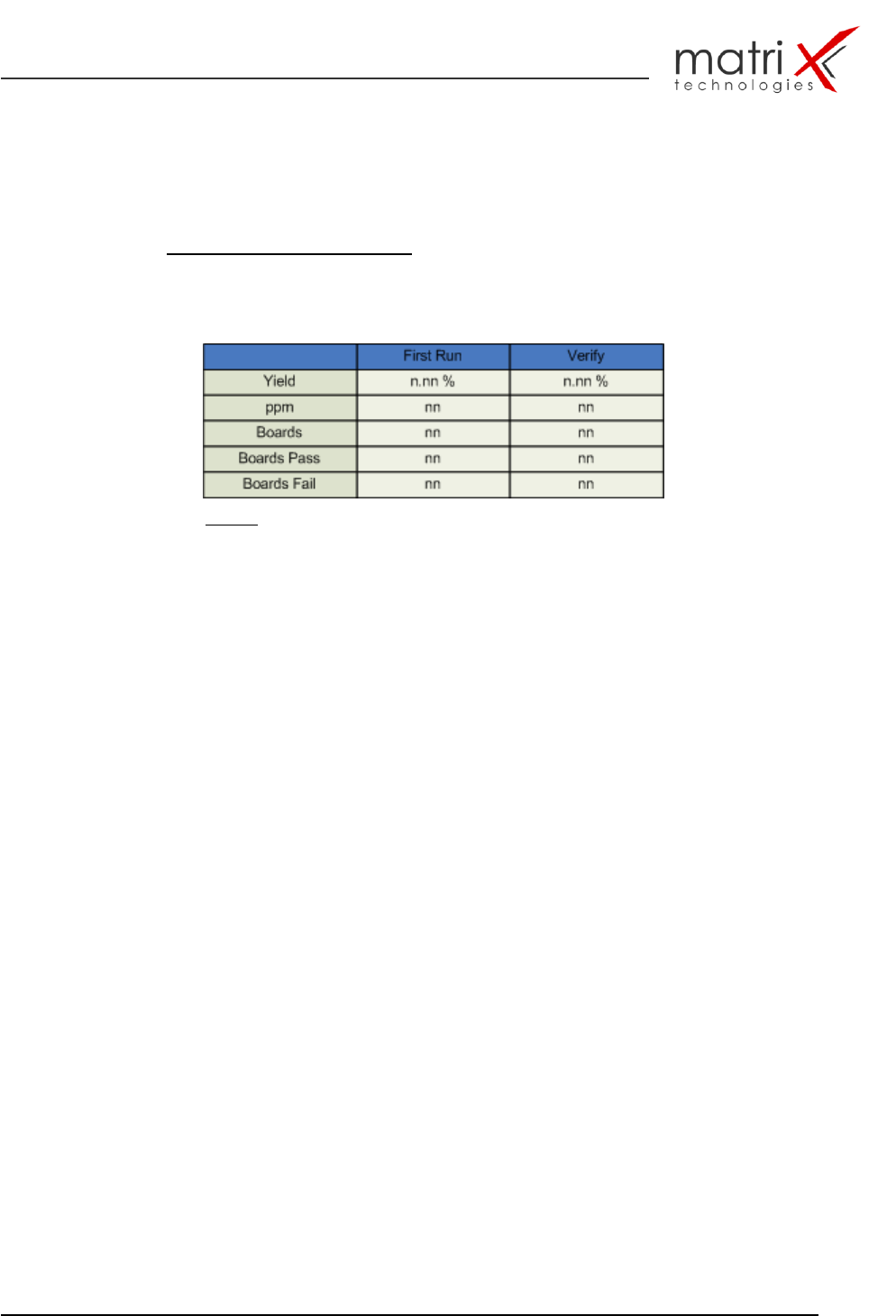
yield/ppm statistic table
Table 7: yield/ppm table
Yield display
…..based on boards or panels, including reject boards, etc.
Yield is given as a percentage of accepted boards. Optionally can the First
Pass Yield (Yield before Verify) enabled and reviewed.
ppm display
The ppm figures are calculated based on joints or components, depending
on the type of defect (Pick & Place vs. solder defect, defined within the
custom defect table).
Per defect (ppm) display
The per defect data could be reviewed graphically or using numbers.
The figures will be given in percent (based on the sum of all defects), or ppm
(using all joints or components as the base)
Automatic process warnings (based on yield, ppm and defect types)
Various, custom definable alarms can be set. If any of them did exceed the
operator has to quit the alarm, prior to continue with normal operations.
This function includes also: a log function for process warnings
Optional:
Graphical defect distribution layout
…displays - based on the graphical CAD layout - the defect distribution of all
selected boards from a specific board type. High number of defects means
large distribution markings.
Top-Ten / Pareto defect statistics
graphical display statistic for defects and part types!
MX-3600 / CXI3600MX / Specification
confidential 29/39 spec_mx3600_sys_10.11.doc
4. MX-3600 / Application Features
4.1. Fiducial Test (Pass Marking Test)
The fiducial test should run before starting inspection of a new PCB sample or
any other sample what has potential fiducial points on it. The fiducial test can
correct the following in-tolerances in the inspection process:
Sample board is not (unparallel,..) in correct loading position
Sample board is slightly bent during clamping
Board warpage, which effects the x-y positions
Board outside dimensions are slightly off as result of an intolerant de-
panelisation process
The following fiducial types can be used:
Layout printed fiducials (dark contrast check) – soldered or unsoldered
like cross points, double cross points, circle, ring, squares, …!
Layout based drilled hole fiducials – like drilling holes and vias.
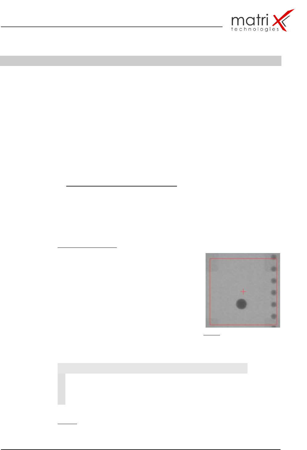
Fiducial test principle:
The fiducial test is correcting the off-positions from
the ideal CAD position coordinates by searching in
a predefined search window the specified fiducial-
pattern (in the example fig. 16 a dark circle) – after
locating the fiducial the object will be centred.
This procedure needs to be done at least at one
more fiducial ideally 3 or 4 fiducials. The detected
centre point coordinates are then processed and
corrected against the machine based cad point
position. The results of the fiducial calculation
process are shown in table 8.
Fig. 16: Fiducial object with search
window and cad point (red cross)
Fiducial test result to be used for X-Y CAD position correction:
Table 8: fiducial test result data
Fiducial Test
1
DeltaX
Corrected Fid. Cad X-Position
2
DeltaY
Corrected Fid. Cad Y-Position
3
FiducialError
= 0 Fid.-object successfully located
= 1 no Fid. Object detected or
multiple objects detected
MX-3600 / CXI3600MX / Specification
confidential 30/39 spec_mx3600_sys_10.11.doc
4.2. MIPS_Inspect / X-RAY Solder Joint Inspection Algorithm
Library (MIPS_SJ-L)
The core of the inspection process is the algorithm library for solder joints and
components.
A detailed description and specification of the algorithm are documented in:
SMT/THT X-RAY Inspection algorithm specification
MX3600-Algorithm Manual
An overview about the inspection capabilities and the defect classes is
documented in:
AppendiX: F Solder joint inspection & component defect library
(attached to this document!)
The classification techniques for the defect detection are shown in
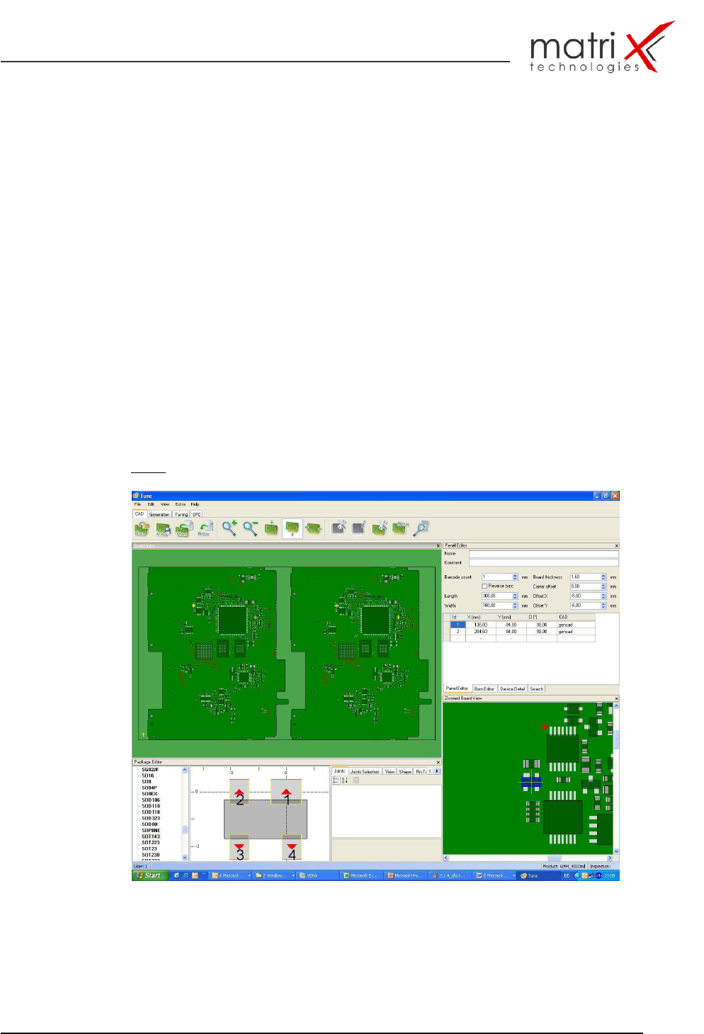
Fig. 17: Inspection program generation with Gencad Cad Import