multifunction-rio-user-manual.pdf - 第15页
Chapter 1 Introduction Multifunction Reconfigur able I/O User Manual 1-6 ni.com The FPGA does not retain the VI when the device is po wered of f, so you must reload the VI each time you po we r on the de vice. Y ou can l…
Chapter 1 Introduction
© National Instruments Corporation 1-5 Multifunction Reconfigurable I/O User Manual
Reconfigurable I/O Architecture
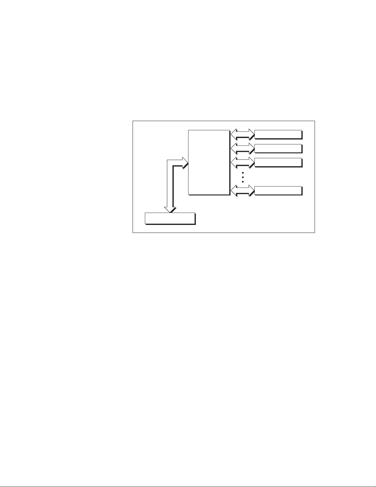
Figure 1-1 shows an FPGA connected to fixed I/O resources and a bus
interface. The fixed I/O resources include A/D converters (ADCs),
D/A converters (DACs), and digital I/O lines.
Figure 1-1. High-Level FPGA Functional Overview
Software accesses the device through the bus interface, and the FPGA
connects the bus interface and the fixed I/O to make possible timing,
triggering, processing, and custom I/O measurements using the LabVIEW
FPGA Module.
The FPGA logic provides timing, triggering, processing, and custom I/O
measurements. Each fixed I/O resource used by the application uses a small
portion of the FPGA logic that controls the fixed I/O resource. The bus
interface also uses a small portion of the FPGA logic to provide software
access to the device.
The remaining FPGA logic is available for higher-level functions such as
timing, triggering, and counting. The functions use varied amounts of logic.
You can place useful applications in the FPGA. How much FPGA space
your application requires depends on your need for I/O recovery, I/O, and
logic algorithms.
FPGA
Bus Interface
Fixed I/O Resource
Fixed I/O Resource
Fixed I/O Resource
Fixed I/O Resource

Chapter 1 Introduction
Multifunction Reconfigurable I/O User Manual 1-6 ni.com
The FPGA does not retain the VI when the device is powered off, so you
must reload the VI each time you power on the device. You can load the VI
from onboard Flash memory or from software over the bus interface. One
advantage to using Flash memory is that the VI can start executing almost
immediately after power up, instead of waiting for the computer to
completely boot and load the FPGA VI. Refer to the LabVIEW Help for
more information about how to store your VI in Flash memory.
Reconfigurable I/O Applications
You can use the LabVIEW FPGA Module to create or acquire new VIs
for your application. The FPGA Module allows you to define custom
functionality for your device using a subset of LabVIEW functionality.
Refer to the examples, available in LabVIEW by selecting Help»Find
Examples, and then selecting Hardware Input and Output»R Series, for
examples of FPGA VIs.
Software Development
You can use LabVIEW with the LabVIEW FPGA Module to program your
device. To develop real-time applications that control your device, use
LabVIEW with the LabVIEW Real-Time Module.
LabVIEW FPGA Module
The LabVIEW FPGA Module enables you to use LabVIEW to create VIs
that run on the FPGA of the R Series target device. Use the FPGA Module
VIs and functions to control the I/O, timing, and logic of your device and
to generate interrupts for synchronization. Select Help»Search the
LabVIEW Help to view the LabVIEW Help. In the LabVIEW Help, use the
Contents tab to browse to the FPGA Interface book for more information
about the FPGA Interface functions.
You can use Interactive Front Panel Communication to communicate
directly with the FPGA VI running on the FPGA target. You can use
Programmatic FPGA Interface Communication to programmatically
control and communicate with FPGA VIs from host VIs.
Use the FPGA Interface functions when you target LabVIEW for Windows
or an RT target to create host VIs that wait for interrupts and control the
FPGA by reading and writing the FPGA VI running on your device.

Chapter 1 Introduction
© National Instruments Corporation 1-7 Multifunction Reconfigurable I/O User Manual
Note If you use the device without the FPGA Module, you can use the RIO Device Setup
utility, available by selecting Start»All Programs»National Instruments»
NI-RIO»RIO Device Setup to download precompiled FPGA VIs to the Flash memory of
the device. This utility installs with NI-RIO. You also can use the utility to configure the
analog input mode, to synchronize the clock on the device to the PXI clock (for PXI-78xx
only), and to configure when the VI loads from Flash memory. For more information about
using the RIO Device Setup utility, refer to the RIO Device Setup Help, found at Start»All
Programs»National Instruments»NI-RIO»
RIO Device Setup Help.
LabVIEW Real-Time Module
The LabVIEW Real-Time Module extends the LabVIEW development
environment to deliver deterministic, real-time performance.
You can write host VIs that run in Windows or on RT targets to
communicate with FPGA VIs that run on your device. You can develop
real-time VIs with LabVIEW and the LabVIEW Real-Time Module, and
then download the VIs to run on a hardware target with a real-time
operating system. The LabVIEW Real-Time Module allows you to use
your device in RT Series PXI systems being controlled in real time by a VI.
The PCI/PXI-781x is designed as a single-point DIO complement to the
LabVIEW Real-Time Module. The PCI/PCIe/PXI-783x/784x/785x is
designed as a single-point AI, AO, and DIO complement to the
LabVIEW Real-Time Module. Refer to the LabVIEW Help, available by
selecting Help»Search the LabVIEW Help, for more information about
the LabVIEW Real-Time Module.