multifunction-rio-user-manual.pdf - 第37页
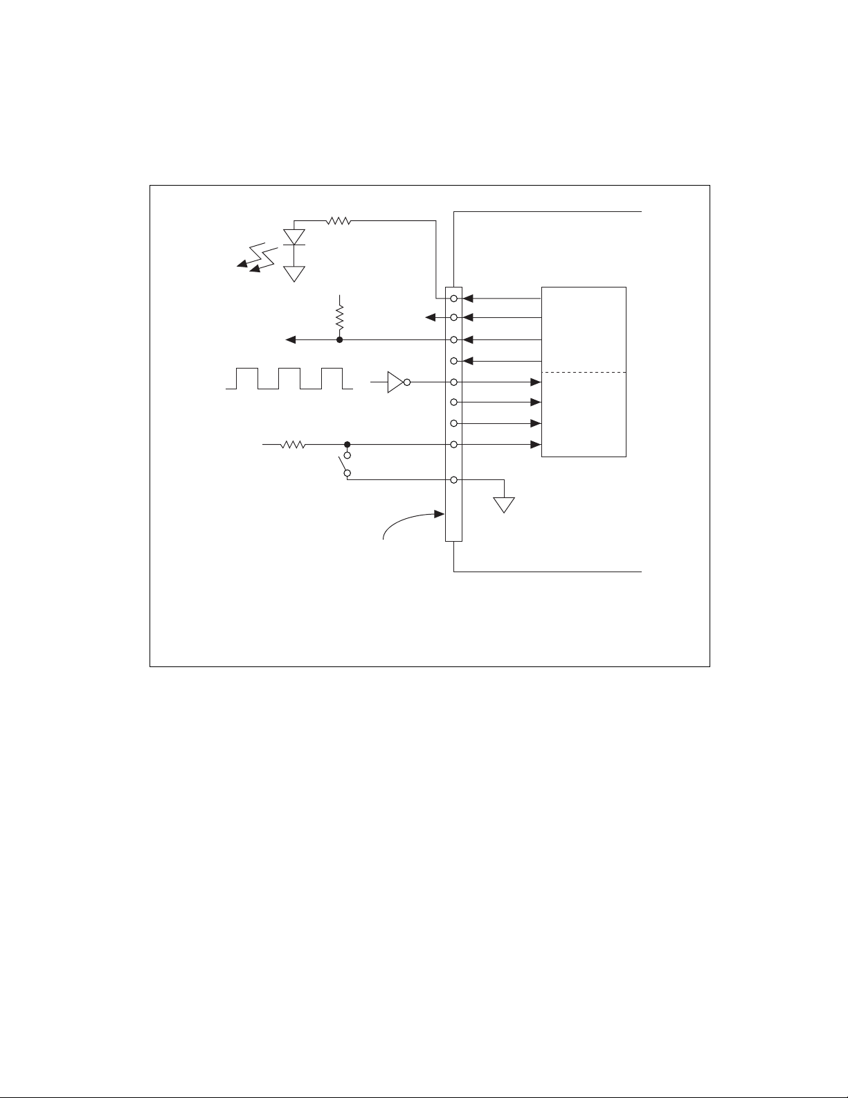
Chapter 2 Hardware Overview of the NI 78x x © National Instruments Corporation 2-19 Multifunction Reconfigurabl e I/O User Manual Figure 2-11. Example Digital I/O Connections Figure 2-11 shows DIO<0..3> configured …
Chapter 2 Hardware Overview of the NI 78xx
Multifunction Reconfigurable I/O User Manual 2-18 ni.com
NI 7831/7833/784x/785x has one RMIO and two RDIO connectors for a
total of 96 DIO lines.
Refer to Figure A-1, NI 781x Connector Pin Assignments and Locations,
for the connector locations and the I/O connector pin assignments on the
NI 781x. Refer to Figure A-2, NI 783x/784x/785x Connector Pin
Assignments and Locations, for the connector locations and the I/O
connector pin assignments on the NI 783x/784x/785x.
The DIO lines on the NI 78xx support various logic levels. When
configured as inputs, they can receive signals from 5 V TTL, 3.3 V LVTTL,
5 V CMOS, and 3.3 V LVCMOS devices. When configured as outputs, they
can send signals to 5 V TTL, 3.3 V LVTTL, and 3.3 V LVCMOS devices.
Because the digital outputs provide a nominal output swing of 0 to 3.3 V
(3.3 V TTL), the DIO lines cannot drive 5 V CMOS logic levels. To
interface to 5 V CMOS devices, you must provide an external pull-up
resistor to 5 V. This resistor pulls up the 3.3 V digital output from the
NI 78xx to 5 V CMOS logic levels. Refer to the Multifunction
Reconfigurable I/O Specifications, available at
ni.com/docs, for detailed
DIO specifications.
Note 5 V is not supported on all NI 78xx products. See the datasheet & specification of
your product by going to
ni.com/shop/category/multifunction-io.html.
Caution
Exceeding the maximum input voltage ratings, listed in Table A-2, NI 78xx I/O
Signal Summary, can damage the NI 78xx and the computer. NI is not liable for any
damage resulting from such signal connections.
Caution Do not short the DIO lines of the NI 78xx directly to power or to ground. Doing
so can damage the NI 78xx by causing excessive current to flow through the DIO lines.
You can connect multiple NI 78xx digital output lines in parallel to provide
higher current sourcing or sinking capability. If you connect multiple
digital output lines in parallel, your application must drive all of these lines
simultaneously to the same value. If you connect digital lines together and
drive them to different values, excessive current can flow through the DIO
lines and damage the NI 78xx. Refer to the Multifunction Reconfigurable
I/O Specifications, available at
ni.com/docs, for more information about
DIO specifications. Figure 2-11 shows signal connections for three typical
DIO applications.
Chapter 2 Hardware Overview of the NI 78xx
© National Instruments Corporation 2-19 Multifunction Reconfigurable I/O User Manual
Figure 2-11. Example Digital I/O Connections
Figure 2-11 shows DIO<0..3> configured for digital input and DIO<4..7>
configured for digital output. Digital input applications include receiving
TTL, LVTTL, CMOS, or LVCMOS signals and sensing external device
states, such as the state of the switch shown in Figure 2-11. Digital output
applications include sending TTL or LVCMOS signals and driving external
devices, such as the LED shown in Figure 2-11.
The NI 78xx SHC68-68-RDIO cable contains individually shielded
bundles that route each digital signal on an individually shielded pair of
wires, and each signal is twisted with its own wire to digital ground.
*
3.3 V CMOS
†
Use a pull-up resistor when driving 5 V CMOS devices.
LED
TTL, LVTTL, CMOS, or LVCMOS Signal
+5 V
Switch
I/O Connector
DGND
NI 783x/784x/785x
DIO<0..3>
DIO<4..7>
+5 V
5 V CMOS
†
TTL or
LVCMOS
*
Compatible
Devices
DGND
Chapter 2 Hardware Overview of the NI 78xx
Multifunction Reconfigurable I/O User Manual 2-20 ni.com
The SHC68-68-RDIO was designed specifically for R Series devices and is
the NI-recommended cable for digital applications. If you are using the
SH68-C68-S cable, however, please note the following considerations.
The SH68-C68-S shielded cable contains 34 twisted pairs of conductors. To
maximize the digital I/O available on the NI 78xx, some of the DIO lines
are twisted with power or ground and some DIO lines are twisted with other
DIO lines. To obtain maximum signal integrity, place edge-sensitive or
high-frequency digital signals on the DIO lines that are paired with power
or ground. Because the DIO lines that are twisted with other DIO lines can
couple noise onto each other, use these lines for static signals or
non-edge-sensitive, low-frequency digital signals. Examples of
high-frequency or edge-sensitive signals include clock, trigger, pulse-width
modulation (PWM), encoder, and counter signals. Examples of static
signals or non-edge-sensitive, low-frequency signals include LEDs,
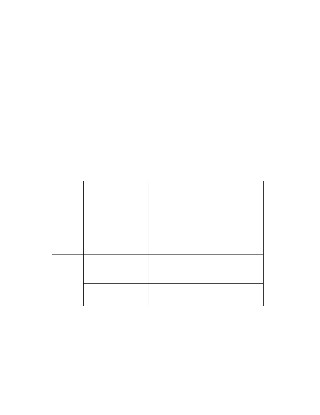
switches, and relays. Table 2-4 summarizes these guidelines.
Table 2-4. DIO Signal Guidelines for the NI 78xx
Device Digital Lines
SH68-C68-S
Shielded Cable
Signal Pairing
Recommended Types
of Digital Signals
NI 781x DIO<0..27> DIO line paired
with power
or ground
All types—high-frequency or
low-frequency signals,
edge-sensitive or
non-edge-sensitive signals
DIO<28..39> DIO line paired
with another
DIO line
Static signals or
non-edge-sensitive,
low-frequency signals
NI 783x,
NI 784x,
NI 785x
Connector 0, DIO<0..7>;
Connector 1, DIO<0..27>;
Connector 2, DIO<0..27>
DIO line paired
with power
or ground
All types—high-frequency or
low-frequency signals,
edge-sensitive or
non-edge-sensitive signals
Connector 0, DIO<8..15>;
Connector 1, DIO<28..39>;
Connector 2, DIO<28..39>
DIO line paired
with another
DIO line
Static signals or
non-edge-sensitive,
low-frequency signals