multifunction-rio-user-manual.pdf - 第32页
Chapter 2 Hardware Overv iew of the NI 78x x Multifunction Reconfigurable I/O U ser Manual 2-14 ni.com Y ou can configure the NI 783 x /784 x /785 x device channels in softw are for RSE or NRSE input modes. Use the RSE i…

Chapter 2 Hardware Overview of the NI 78xx
© National Instruments Corporation 2-13 Multifunction Reconfigurable I/O User Manual
line to AIGND, connect it to AIGND through a resistor that is about
100 times the equivalent source impedance. The resistor puts the signal
path nearly in balance. About the same amount of noise couples onto both
connections, which yields better rejection of electrostatically coupled
noise. Also, this input mode does not load down the source, other than the
very high-input impedance of the instrumentation amplifier.
You can fully balance the signal path by connecting another resistor of the
same value between the positive input and AIGND, as shown in Figure 2-7.
This fully balanced input mode offers slightly better noise rejection but has
the disadvantage of loading down the source with the series combination
(sum) of the two resistors. If, for example, the source impedance is 2 kΩ
and each of the two resistors is 100 kΩ, the resistors load down the source
with 200 kΩ and produce a –1% gain error.
Both inputs of the instrumentation amplifier require a DC path to ground
for the instrumentation amplifier to work. If the source is AC coupled
(capacitively coupled), the instrumentation amplifier needs a resistor
between the positive input and AIGND. If the source has low-impedance,
choose a resistor that is large enough not to significantly load the source but
small enough not to produce significant input offset voltage as a result of
input bias current, typically 100 kΩ to 1 MΩ. In this case, connect the
negative input directly to AIGND. If the source has high output impedance,
balance the signal path as previously described using the same value
resistor on both the positive and negative inputs. Loading down the source
causes some gain error.
Single-Ended Connection Considerations
When an NI 783x/784x/785x AI signal is referenced to a ground that can be
shared with other input signals, it forms a single-ended connection. The
input signal connects to the positive input of the instrumentation amplifier
and the ground connects to the negative input of the instrumentation
amplifier.
You can use single-ended input connections for any input signal that meets
the following conditions:
• The input signal is high-level (>1 V).
• The leads connecting the signal to the device are less than 3 m (10 ft).
• The input signal can share a common reference point with other
signals.
Use DIFF input connections for greater signal integrity for any input signal
that does not meet the preceding conditions.
Chapter 2 Hardware Overview of the NI 78xx
Multifunction Reconfigurable I/O User Manual 2-14 ni.com
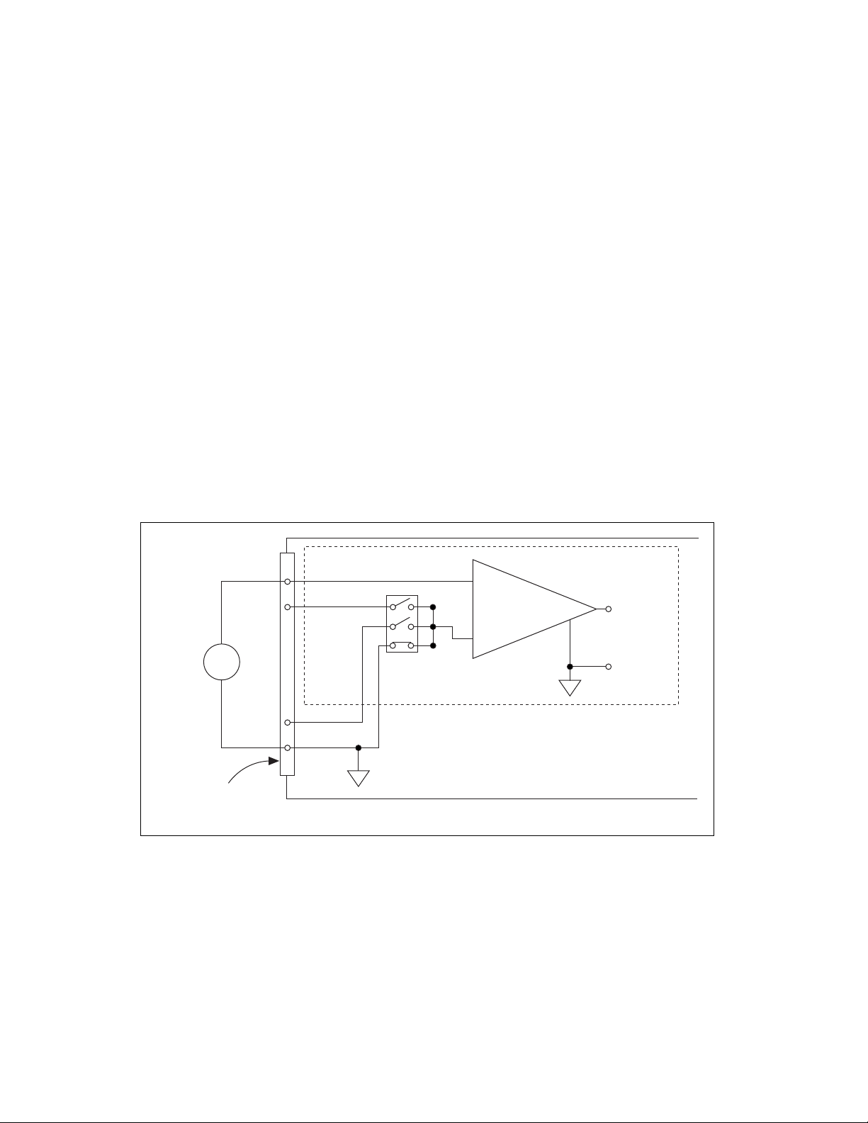
You can configure the NI 783x/784x/785x device channels in software for
RSE or NRSE input modes. Use the RSE input mode for floating signal
sources. In this case, the device provides the reference ground point for the
external signal. Use the NRSE input mode for ground-referenced signal
sources. In this case, the external signal supplies its own reference ground
point and the device should not supply one.
In single-ended input modes, electrostatic and magnetic noise couples into
the signal connections more than in differential input modes. The coupling
is the result of differences in the signal path. Magnetic coupling
is proportional to the area between the two signal conductors. Electrical
coupling is a function of how much the electric field differs between the
two conductors.
Single-Ended Connections for Floating Signal
Sources (RSE Input Mode)
Figure 2-8 shows how to connect a floating signal source to a channel on
the NI 783x/784x/785x configured for RSE input mode.
Figure 2-8. Single-Ended Input Connections for Nonreferenced or Floating Signals
–
+
–
+
–
+
I/O Connector
AISENSE
AIGND
V
m
AI+
AI–
V
s
Floating
Signal
Source
Instrumentation
Amplifier
Measured
Voltage
RSE Input Mode Selected
Chapter 2 Hardware Overview of the NI 78xx
© National Instruments Corporation 2-15 Multifunction Reconfigurable I/O User Manual
Single-Ended Connections for Grounded Signal
Sources (NRSE Input Mode)
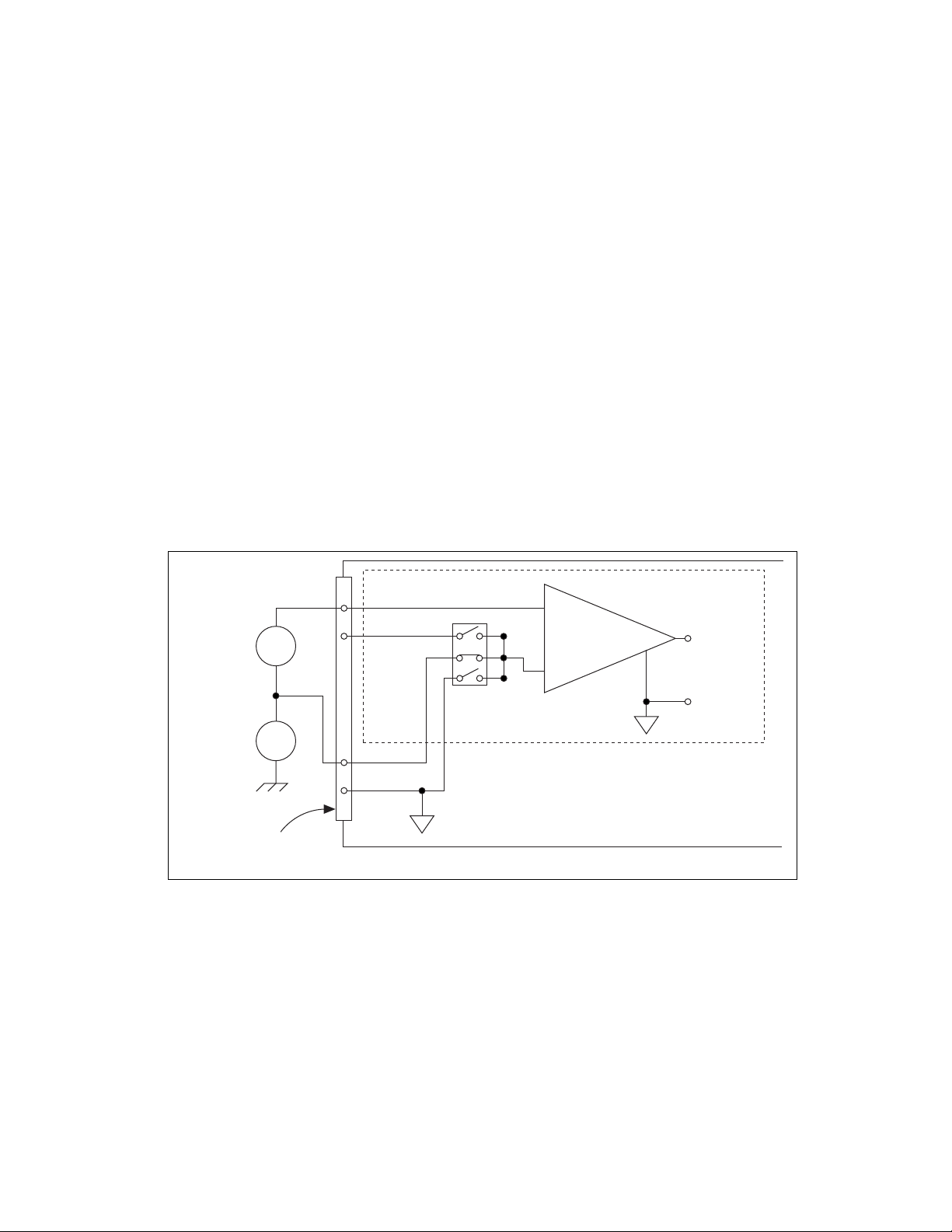
To measure a grounded signal source with a single-ended input mode, you
must configure the NI 783x/784x/785x in the NRSE input mode. Then
connect the signal to the positive input of the NI 783x/784x/785x
instrumentation amplifier and connect the signal local ground reference to
the negative input of the instrumentation amplifier. The ground point of the
signal should be connected to AISENSE. Any potential difference between
the NI 783x/784x/785x ground and the signal ground appears as a
common-mode signal at both the positive and negative inputs of the
instrumentation amplifier. The instrumentation amplifier rejects this
difference. If the input circuitry of a NI 783x/784x/785x is referenced to
ground in RSE input mode, this difference in ground potentials appears as
an error in the measured voltage.
Figure 2-9 shows how to connect a grounded signal source to a channel on
the NI 783x/784x/785x configured for NRSE input mode.
Figure 2-9. Single-Ended Input Connections for Ground-Referenced Signals
–
+
–
+
–
+
–
+
V
cm
V
s
I/O Connector
AISENSE
AIGND
V
m
AI+
AI–
Instrumentation
Amplifier
Measured
Voltage
Ground-
Referenced
Signal
Source
Common-
Mode
Noise and
Ground
Potential
NRSE Input Mode Selected