multifunction-rio-user-manual.pdf - 第26页
Chapter 2 Hardware Overv iew of the NI 78x x Multifunction Reconfigur able I/O User Manual 2-8 ni.com T ypes of Signal Sources When configuring t he input channels and making signal connections, you must first det ermine…
Chapter 2 Hardware Overview of the NI 78xx
© National Instruments Corporation 2-7 Multifunction Reconfigurable I/O User Manual
Connection of AI signals to the NI 783x/784x/785x depends on the input
mode of the AI channels you are using and the type of input signal source.
With different input modes, you can use the instrumentation amplifier in
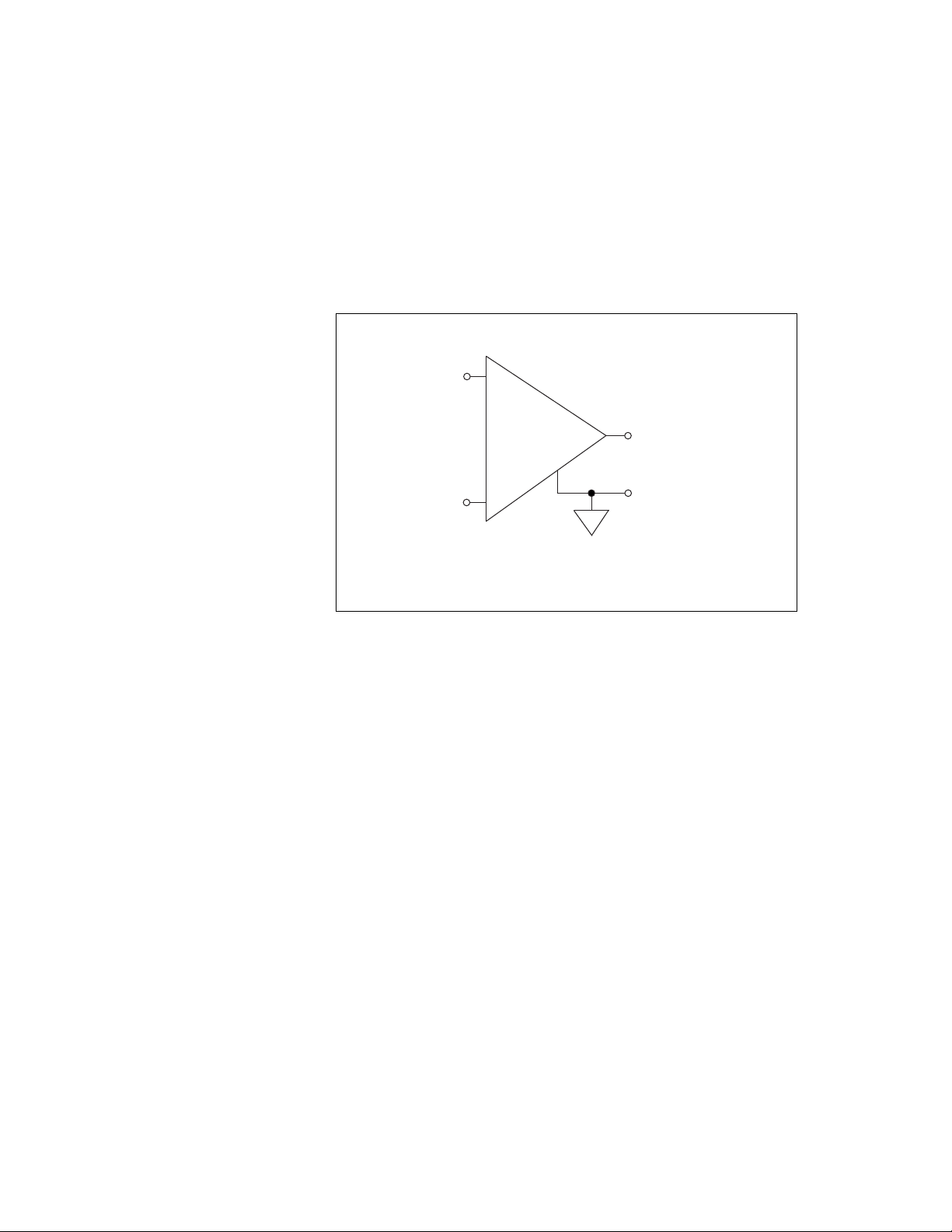
different ways. Figure 2-4 shows a diagram of the device instrumentation
amplifier.
Figure 2-4. NI 783x/784x/785x Instrumentation Amplifier
The instrumentation amplifier applies common-mode voltage rejection
and presents high input impedance to the AI signals connected to the
NI 783x/784x/785x. Input multiplexers on the device route signals to the
positive and negative inputs of the instrumentation amplifier. The
instrumentation amplifier converts two input signals to a signal that is the
difference between the two input signals. The amplifier output voltage is
referenced to the device ground. The device ADC measures this output
voltage when it performs A/D conversions.
You must reference all signals to ground either at the source device or at the
NI 783x/784x/785x. If you have a floating source, reference the signal to
ground by using RSE input mode or the DIFF input mode with bias
resistors. Refer to the Differential Connections for Nonreferenced or
Floating Signal Sources section of this chapter for more information about
these input modes. If you have a grounded source, do not reference the
signal to AIGND. You can avoid this reference by using DIFF or NRSE
input modes.
+
+
–
–
V
m
= [V
in+
– V
in–
]
V
in+
V
in–
V
m
Instrumentation
Amplifier
Measured
Voltage

Chapter 2 Hardware Overview of the NI 78xx
Multifunction Reconfigurable I/O User Manual 2-8 ni.com
Types of Signal Sources
When configuring the input channels and making signal connections,
you must first determine whether the signal sources are floating or ground
referenced. The following sections describe these two signal types.
Floating Signal Sources
A floating signal source is not connected to the building ground system but
instead has an isolated ground-reference point. Some examples of floating
signal sources are outputs of transformers, thermocouples, battery-powered
devices, optical isolator outputs, and isolation amplifiers. An instrument
or device that has an isolated output is a floating signal source.
You must connect the ground reference of a floating signal to the
NI 783x/784x/785x AIGND through a bias resistor to establish a local or
onboard reference for the signal. Otherwise, the measured input signal
varies as the source floats out of the common-mode input range.
Ground-Referenced Signal Sources
A ground-referenced signal source is connected to the building system
ground, so it is already connected to a common ground point with respect
to the NI 783x/784x/785x, assuming that the computer is plugged into the
same power system. Instruments or devices with nonisolated outputs that
plug into the building power system are ground referenced signal sources.
The difference in ground potential between two instruments connected to
the same building power system is typically between 1 and 100 mV. This
difference can be much higher if power distribution circuits are improperly
connected. If a grounded signal source is improperly measured, this
difference might appear as a measurement error. The connection
instructions for grounded signal sources are designed to eliminate this
ground potential difference from the measured signal.
Input Modes
The following sections discuss single-ended and differential measurements
and considerations for measuring both floating and ground-referenced
signal sources.
Chapter 2 Hardware Overview of the NI 78xx
© National Instruments Corporation 2-9 Multifunction Reconfigurable I/O User Manual
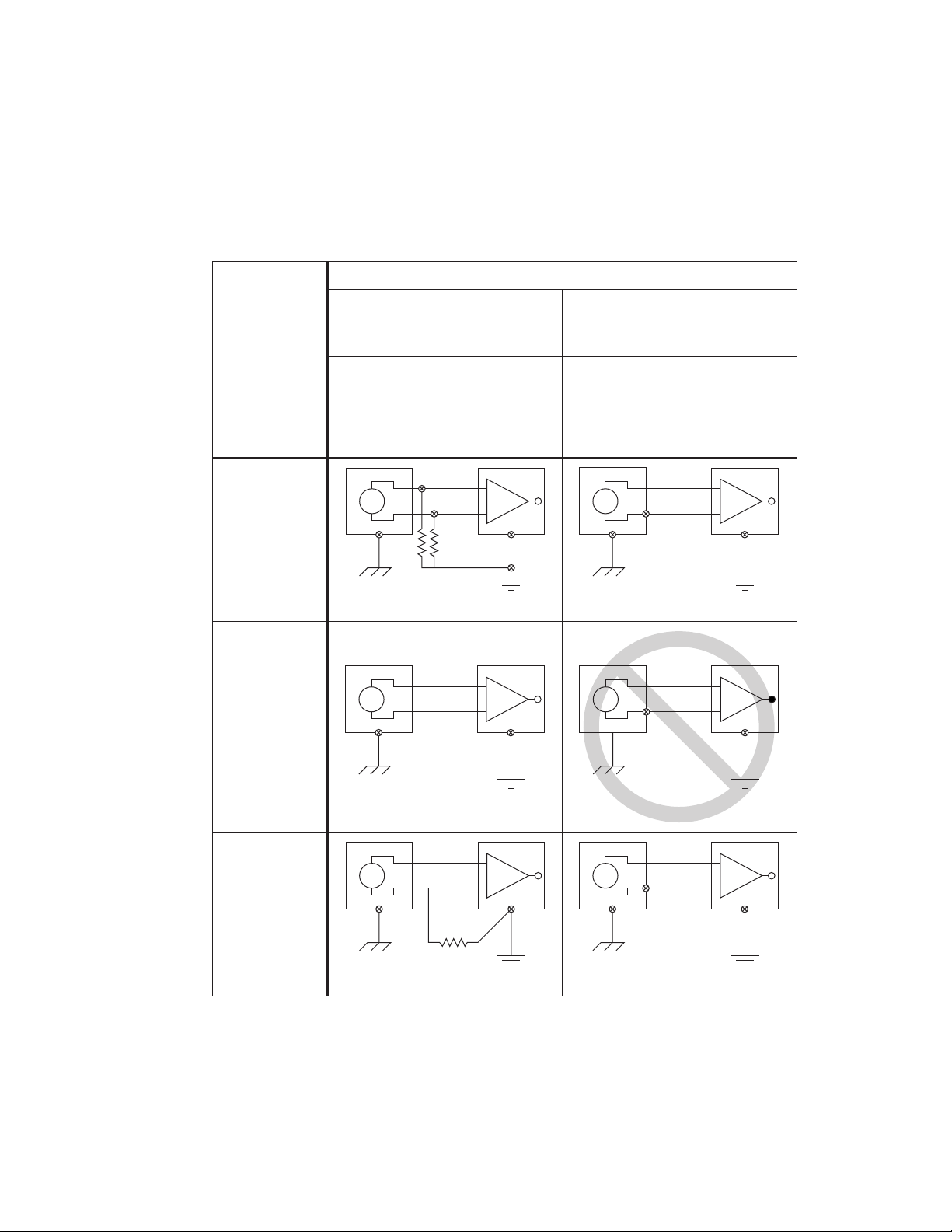
Figure 2-5 summarizes the recommended input mode for both types of
signal sources.
Figure 2-5. Summary of Analog Input Connections
+
–
+
–
V
1
AI<i>
AISENSE
AIGND<i>
+
–
+
–
V
1
AI<i>
AISENSE
AIGND<i>
See text for information on bias resistors.
+
–
+
–
V
1
AI<i>
AIGND<i>
+
–
+
–
V
1
AI
+ V
g
–
AIGND
Ground-loop losses, V
g
, are added to
measured signal.
NOT RECOMMENDED
+
–
+
–
V
1
AI<i>(+)
AI<i>(–)
AIGND<i>
+
–
+
–
V
1
AI<i>(+)
AI<i>(–)
AIGND<i>
See text for information on bias resistors.
Signal Source Type
Floating Signal Source
(Not Connected to Building Ground)
Grounded Signal Source
Examples
• Ungrounded Thermocouples
• Signal Conditioning with
Isolated Outputs
• Battery Devices
Examples
• Plug-in Instruments with
Nonisolated Outputs
Input
Differential
(DIFF)
Single-Ended—
Ground
Referenced
(RSE)
Single-Ended—
Nonreferenced
(NRSE)