multifunction-rio-user-manual.pdf - 第42页
Chapter 2 Hardware Overv iew of the NI 78x x Multifunction Reconfigurable I/O U ser Manual 2-24 ni.com Figure 2-13. Switch Location on the PCI-781 x Figure 2-14. Switch Location on the PXI-781 x SW1, SW2, SW3 N I PX I- 7…
Chapter 2 Hardware Overview of the NI 78xx
© National Instruments Corporation 2-23 Multifunction Reconfigurable I/O User Manual
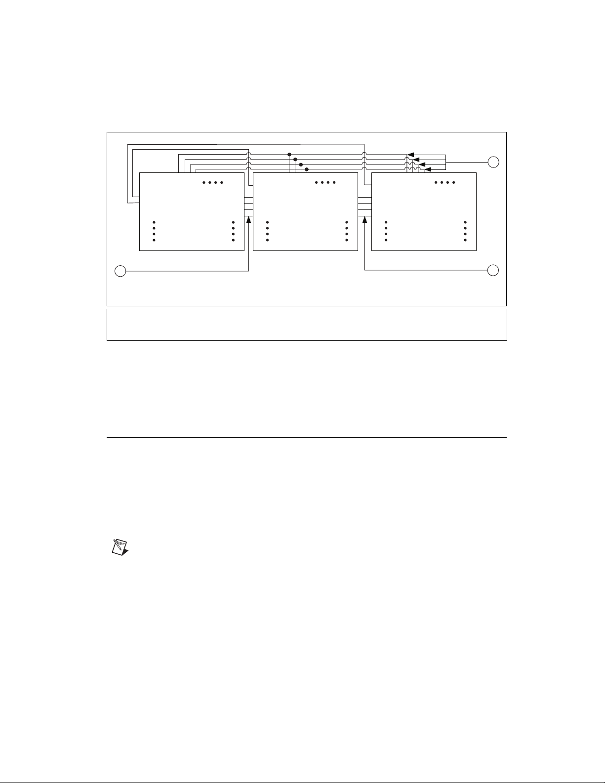
Figure 2-12. PXI Star Trigger Connections in a PXI Chassis
Refer to the PXI Hardware Specification Revision 2.1 and PXI Software
Specification Revision 2.1 at
www.pxisa.org for more information about
PXI triggers.
Switch Settings (NI 781x /783x Only)
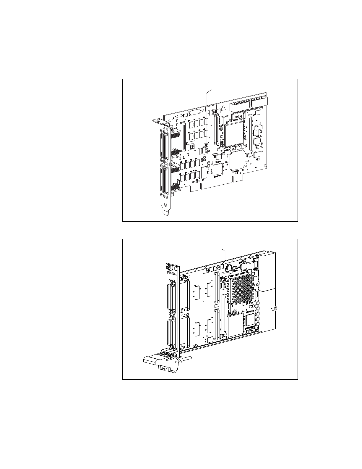
Refer to Figure 2-13 for the location of switches on the PCI-781x and
Figure 2-14 for the location of switches on the PXI-781x. Refer
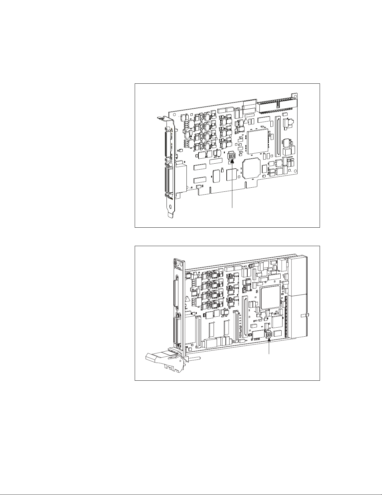
to Figure 2-15 for the location of switches on the PCI-783x and Figure 2-16
for the location of switches on the PXI-783x. For normal operation, SW1 is
in the OFF position. To prevent a VI stored in Flash memory from loading
to the FPGA at power up, move SW1 to the ON position, as shown in
Figure 2-17.
Note SW2 and SW3 are not connected.
1 Shared Local Bus Lines between Slot 2 and Slot 3
2 Shared Trigger Lines between Slot 2, Slot 3, and Slot 4
3Shared Local Bus Lines between Slot 3 and Slot 4
Lbr0
Lbr1
Lbr2
Lbr3
PXI_Star*
Slot 2
Lbl0
Lbl1
Lbl2
Lbl3
Lbr0
Lbr1
Lbr2
Lbr3
PXI_Star
Slot 3
Lbl0
Lbl1
Lbl2
Lbl3
Lbr0
Lbr1
Lbr2
Lbr3
PXI_Star
Slot 4
3
1
2
* A Slot 2 device ties the PXI_Star Line to the PXI 10 MHz clock
Lbl0
Lbl1
Lbl2
Lbl3
Trigger 0
Trigger 1
Trigger 2
Trigger 3
Trigger 0
Trigger 1
Trigger 2
Trigger 3
Trigger 0
Trigger 1
Trigger 2
Trigger 3
Chapter 2 Hardware Overview of the NI 78xx
Multifunction Reconfigurable I/O User Manual 2-24 ni.com
Figure 2-13. Switch Location on the PCI-781x
Figure 2-14. Switch Location on the PXI-781x
SW1, SW2, SW3
N
I PX
I-
7811R
Reconfigurab
le I/O
CONNECTOR 2 (DIO)CONNECTOR 3 (DIO)
SW1, SW2, SW3
Chapter 2 Hardware Overview of the NI 78xx
© National Instruments Corporation 2-25 Multifunction Reconfigurable I/O User Manual
Figure 2-15. Switch Location on the PCI-783x
Figure 2-16. Switch Location on the PXI-783x
SW1, SW2, SW3
SW1, SW2, SW3
CONNECTOR 2 (DIO)
NI PXI-7831R
Reconfigurable I/O