multifunction-rio-user-manual.pdf - 第47页
Chapter 2 Hardware Overview of the NI 78x x © National Instruments Corporation 2-29 Multifunction Reconfigurabl e I/O User Manual Disk Drive Power Co nnector Installation Before installing the disk drive po wer connector…
Chapter 2 Hardware Overview of the NI 78xx
Multifunction Reconfigurable I/O User Manual 2-28 ni.com
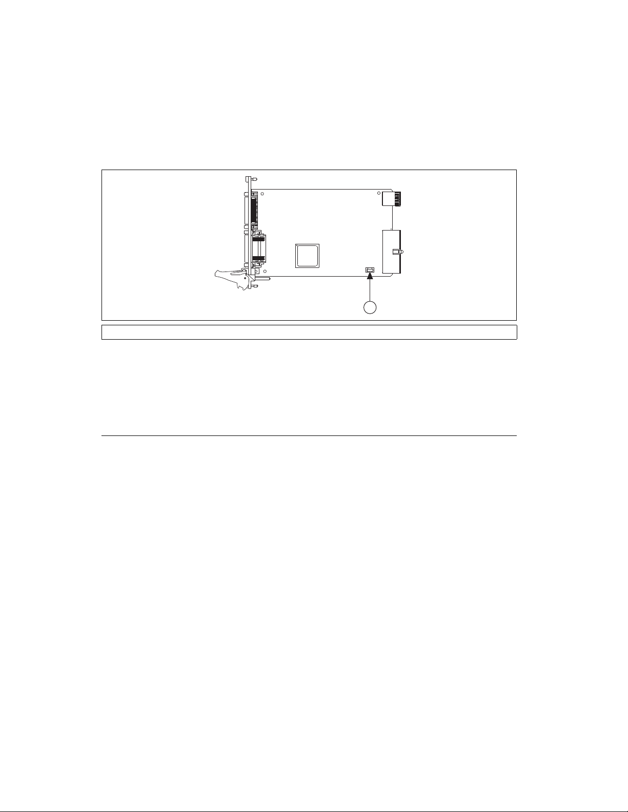
3. Replace the blown fuse while referring to Figure 2-18 for the fuse
locations.
Figure 2-18. NI 784x/785x Replacement Fuse Location
(Littelfuse Part Number 0453004)
4. Reinstall the PCI, PCI Express, or PXI device into the computer or PXI
chassis.
PCI Express Device Disk Drive Power Connector
(PCIe-784x/785x Devices) The disk drive power connector is a four-pin hard
drive connector on PCI Express devices that, when connected, increases the
current the device can supply on the +5 V terminal.
When to Use the Disk Drive Power Connector
PCI Express R Series devices without the disk drive power connector
installed perform identically to other R Series devices for most applications
and with most accessories. For most applications, it is not necessary to
install the disk drive power connector.
However, you should install the disk drive power connector in either of the
following situations:
• You need more power than listed in the device specifications
• You are using an R Series accessory with no external power supply,
such as the cRIO-9151
Refer to the specifications document for your device for more information
about PCI Express power requirements and power limits.
1PCIe-784x/785x Fuse Location 2PXI-784x/785x Fuse Location
1
Chapter 2 Hardware Overview of the NI 78xx
© National Instruments Corporation 2-29 Multifunction Reconfigurable I/O User Manual
Disk Drive Power Connector Installation
Before installing the disk drive power connector, you must install and set
up the R Series PCI Express device as described in the Getting Started with
R Series Multifunction RIO document. Complete the following steps to
install the disk drive power connector.
1. Power off and unplug the computer.
2. Remove the computer cover.
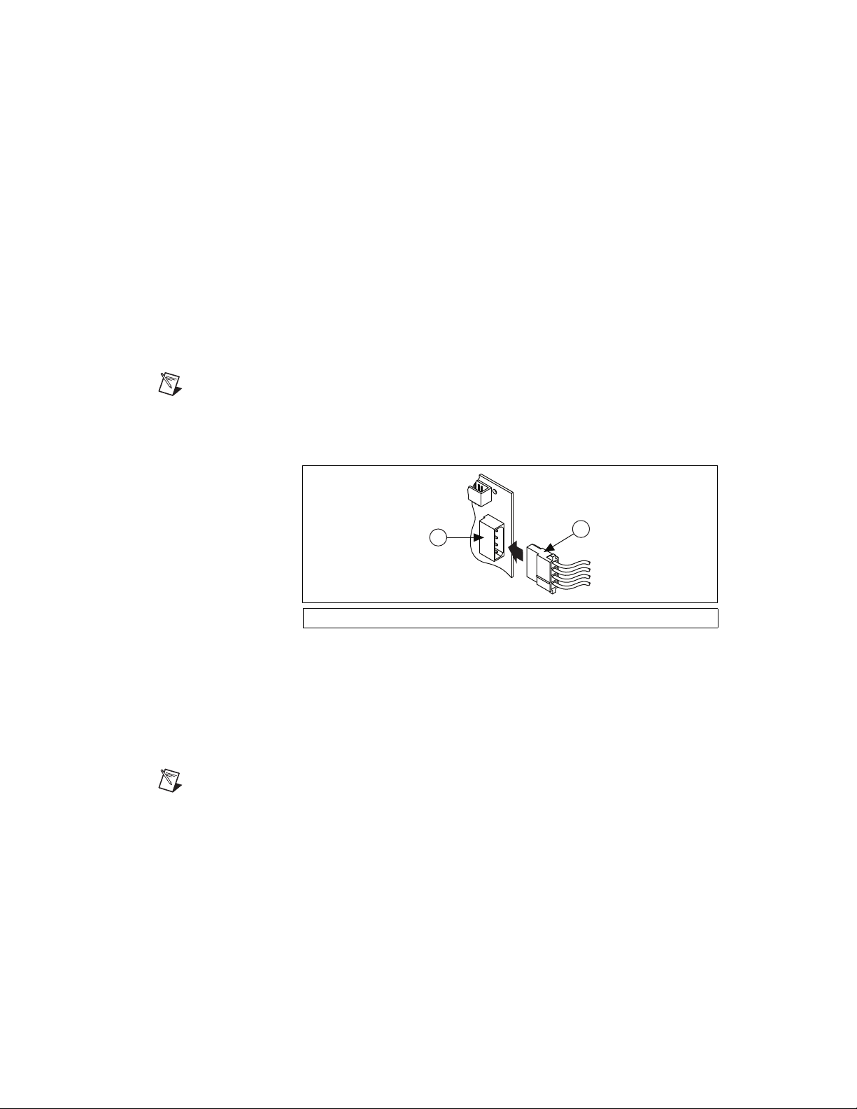
3. Attach the PC disk drive power connector to the disk drive power
connector on the device, as shown in Figure 2-19.
Note The power available on the disk drive power connectors in a computer can vary. For
example, consider using a disk drive power connector that is not in the same power chain
as the hard drive.
Figure 2-19. Connecting to the Disk Drive Power Connector
4. Replace the computer cover, and plug in and power on the computer.
5. Use the NI 78xx Calibration Utility to run a self-calibration on the
PCIe-784x/785x device. Refer to the Self-Calibration section of
Chapter 3, Calibration (NI 783x/784x/785x Only), for more
information.
Note Connecting or disconnecting the disk drive power connector can affect the analog
performance of your device. To compensate for this, NI recommends that you
self-calibrate after connecting or disconnecting the disk drive power connector.
1 Device Disk Drive Power Connector 2 PC Disk Drive Power Connector
1
2

Chapter 2 Hardware Overview of the NI 78xx
Multifunction Reconfigurable I/O User Manual 2-30 ni.com
Field Wiring Considerations (NI 783x /784x /785x Only)
Environmental noise can seriously affect the measurement accuracy of the
device if you do not take proper care when running signal wires between
signal sources and the device. The following recommendations mainly
apply to AI signal routing to the device, as well as signal routing in general.
Take the following precautions to minimize noise pickup and maximize
measurement accuracy:
• Use differential AI connections to reject common-mode noise.
• Use individually shielded, twisted-pair wires to connect AI signals to
the device. With this type of wire, the signals attached to the positive
and negative inputs are twisted together and then covered with a shield.
You then connect this shield only at one point to the signal source
ground. This kind of connection is required for signals traveling
through areas with large magnetic fields or high electromagnetic
interference.
• Route signals to the device carefully. Keep cabling away from noise
sources. The most common noise source in a PXI DAQ system is the
video monitor. Keep the monitor and the analog signals as far apart as
possible.
Use the following recommendations for all signal connections to the
NI 783x/784x/785x:
• Separate NI 783x/784x/785x signal lines from high-current or
high-voltage lines. These lines can induce currents in or voltages on
the device signal lines if they run in parallel paths at a close distance.
To reduce the magnetic coupling between lines, separate them by a
reasonable distance if they run in parallel or run the lines at right angles
to each other.
•Do not run signal lines through conduits that also contain power lines.
• Protect signal lines from magnetic fields caused by electric motors,
welding equipment, breakers, or transformers by running them
through special metal conduits.
Refer to the NI Developer Zone tutorial, Field Wiring and Noise
Considerations for Analog Signals, at
ni.com/zone for more information.