multifunction-rio-user-manual.pdf - 第57页
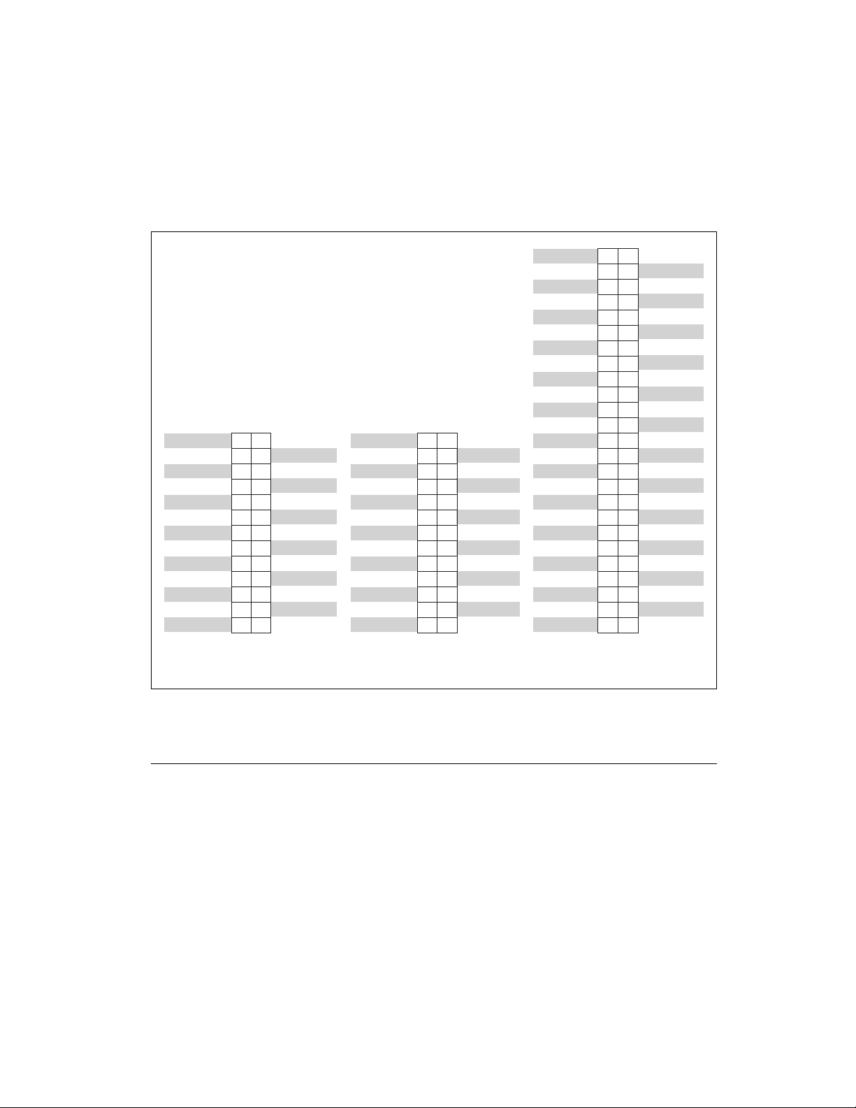
Appendix A Connecting I/O Signals © National Instruments Corporation A-7 Mult ifunction Reconfigurable I/O User Manual Figure A-3 shows the connector pinouts when us ing the NSC68-262650 cable. Figure A-3. Connector Pino…

Appendix A Connecting I/O Signals
Multifunction Reconfigurable I/O User Manual A-6 ni.com
Connecting to 5B and SSR Analog Signal Conditioning
(NI 783x /784x /785x Only)
NI provides cables that allow you to connect signals from the
NI 783x/784x/785x directly to 5B backplanes for analog signal
conditioning and SSR backplanes for digital signal conditioning.
The NSC68-262650 cable connects the signals on the NI 783x/784x/785x
RMIO connector directly to 5B and SSR backplanes. This cable has a
68-pin male VHDCI connector on one end that plugs into the
NI 783x/784x/785x RMIO connector. The other end of this cable provides
two 26-pin female headers plus one 50-pin female header.
One of the 26-pin headers contains all the NI 783x/784x/785x analog input
signals. You can plug this connector directly into a 5B backplane for analog
input signal conditioning. The NI 783x/784x/785x AI<0..n> correspond to
the 5B backplane channels <0..n> in sequential order. Configure the AI
channels to use the NRSE input mode when using 5B signal conditioning.
The other 26-pin header contains all the NI 783x/784x/785x analog output
signals. You can plug this connector directly into a 5B backplane for AO
signal conditioning. The NI 783x/784x/785x AO<0..n> correspond to the
5B backplane channels <0..n> in sequential order.
The 50-pin header contains the 16 DIO lines available on the
NI 783x/784x/785x RMIO connector. You can plug this header directly into
an SSR backplane for digital signal conditioning. DIO lines <0..15>
correspond to the 5B backplane Slots <0..15> in sequential order.
The 5B connector pinouts are compatible with 8-channel 5B08 backplanes
and 16-channel 5B01 backplanes. The NI 7830 can accept analog
input from the first four channels of a 16-channel backplane.
The NI 7831/7833/784x/785x can accept analog input from the
first eight channels of a 16-channel backplane. The SSR connector pinout
is compatible with 8-, 16-, 24-, and 32-channel SSR backplanes. You can
connect to an SSR backplane containing a number of channels unequal to
the 16 DIO lines available on the 50-pin header. In this case, you have
access to only the channels that exist on both the SSR backplane and the
NSC68-262650 cable 50-pin header.
Appendix A Connecting I/O Signals
© National Instruments Corporation A-7 Multifunction Reconfigurable I/O User Manual
Figure A-3 shows the connector pinouts when using the NSC68-262650
cable.
Figure A-3. Connector Pinouts when Using NSC68-262650 Cable
Connecting to SSR Digital Signal Conditioning
NI provides cables that allow you to connect signals from the NI 78xx
directly to SSR backplanes for digital signal conditioning.
The NSC68-5050 cable connects the signals on the NI 78xx RDIO
connectors directly to SSR backplanes for digital signal conditioning. This
cable has a 68-pin male VHDCI connector on one end that plugs into the
NI 78xx RDIO connectors. The other end of this cable provides
two 50-pin female headers.
2
4
6
8
10
12
14
16
18
20
22
24
26
1
3
5
7
9
11
13
15
17
19
21
23
25
AO0
AOGND0
AO1
AO2
AOGND2
AO3
AO4
AOGND4
AO5
AO6
AOGND6
AO7
No
Connect
No
Connect
No
Connect
AOGND1
No
Connect
No
Connect
AOGND3
No
Connect
No
Connect
AOGND5
No
Connect
No
Connect
AOGND7
No
Connect
2
4
6
8
10
12
14
16
18
20
22
24
26
1
3
5
7
9
11
13
15
17
19
21
23
25
AI0+
AIGND0
AI1+
AI2+
AIGND2
AI3+
AI4+
AIGND4
AI5+
AI6+
AIGND6
AI7+
AISENSE
AI0–
AI1–
AIGND1
AI2–
AI3–
AIGND3
AI4–
AI5–
AIGND5
AI6–
AI7–
AIGND7
No
Connect
AI 0–7 Connector
Pin Assignment
2
4
6
8
10
12
14
16
18
20
22
24
26
28
30
32
34
36
38
40
42
44
46
48
50
1
3
5
7
9
11
13
15
17
19
21
23
25
27
29
31
33
35
37
39
41
43
45
47
49
No
Connect
No
Connect
No
Connect
No
Connect
No
Connect
No
Connect
No
Connect
No
Connect
DIO15
DIO14
DIO13
DIO12
DIO11
DIO10
DIO9
DIO8
DIO7
DIO6
DIO5
DIO4
DIO3
DIO2
DIO1
DIO0
+5V
No
Connect
No
Connect
No
Connect
No
Connect
No
Connect
No
Connect
No
Connect
No
Connect
No
Connect
No
Connect
No
Connect
No
Connect
No
Connect
No
Connect
No
Connect
No
Connect
No
Connect
DGND
DGND
DGND
DGND
DGND
DGND
DGND
DGND
DIO 0–15 Connector
Pin Assignment
AO 0–7 Connector
Pin Assignment
Appendix A Connecting I/O Signals
Multifunction Reconfigurable I/O User Manual A-8 ni.com
You can plug each of these 50-pin headers directly into an 8-, 16-, 24-,
or 32-channel SSR backplane for digital signal conditioning. One of the
50-pin headers contains DIO<0..23> from the NI 78xx RDIO connector.
These lines correspond to Slots <0..23> on an SSR backplane in sequential
order. The other 50-pin header contains DIO<24..39> from the NI 78xx
RDIO connector. These lines correspond to Slots <0..15> on an SSR
backplane in sequential order. You can connect to an SSR backplane
containing a number of channels unequal to the number of lines on the
NSC68-5050 cable header. In this case, you have access only to the
channels that exist on both the SSR backplane and the NSC68-5050 cable
header you are using.
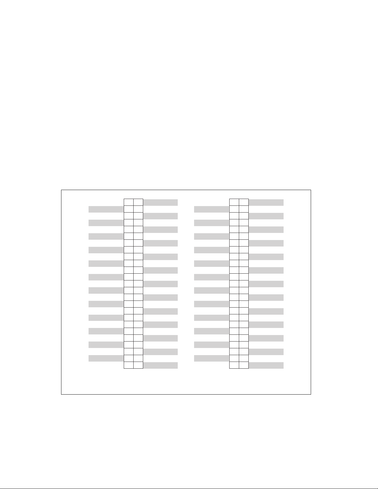
Figure A-4 shows the connector pinouts when using the NSC68-5050
cable.
Figure A-4. Connector Pinouts when Using the NSC68-5050 Cable
2
4
6
8
10
12
14
16
18
20
22
24
26
28
30
32
34
36
38
40
42
44
46
48
50
1
3
5
7
9
11
13
15
17
19
21
23
25
27
29
31
33
35
37
39
41
43
45
47
49
DIO23
DIO22
DIO21
DIO20
DIO19
DIO18
DIO17
DIO16
DIO15
DIO14
DIO13
DIO12
DIO11
DIO10
DIO9
DIO8
DIO7
DIO6
DIO5
DIO4
DIO3
DIO2
DIO1
DIO0
+5V
No Connect
No Connect
No Connect
No Connect
No Connect
No Connect
No Connect
No Connect
No Connect
DGND
DGND
DGND
DGND
DGND
DGND
DGND
DGND
DGND
DGND
DGND
DGND
DGND
DGND
DGND
DGND
2
4
6
8
10
12
14
16
18
20
22
24
26
28
30
32
34
36
38
40
42
44
46
48
50
1
3
5
7
9
11
13
15
17
19
21
23
25
27
29
31
33
35
37
39
41
43
45
47
49
No Connect
No Connect
No Connect
No Connect
No Connect
No Connect
No Connect
No Connect
DIO39
DIO38
DIO37
DIO36
DIO35
DIO34
DIO33
DIO32
DIO31
DIO30
DIO29
DIO28
DIO27
DIO26
DIO25
DIO24
+5V
No Connect
No Connect
No Connect
No Connect
No Connect
No Connect
No Connect
No Connect
No Connect
No Connect
No Connect
No Connect
No Connect
No Connect
No Connect
DGND
DGND
DGND
DGND
DGND
DGND
DGND
DGND
DGND
DGND
DIO 0–23 Connector
Pin Assignment
DIO 24–39 Connector
Pin Assignment