multifunction-rio-user-manual.pdf - 第28页
Chapter 2 Hardware Overv iew of the NI 78x x Multifunction Reconfigurable I/O U ser Manual 2-10 ni.com Differential Connection Consid erations (DIFF Input Mode) In DIFF input mode, the NI 783 x /784 x /7 85 x device meas…
Chapter 2 Hardware Overview of the NI 78xx
© National Instruments Corporation 2-9 Multifunction Reconfigurable I/O User Manual
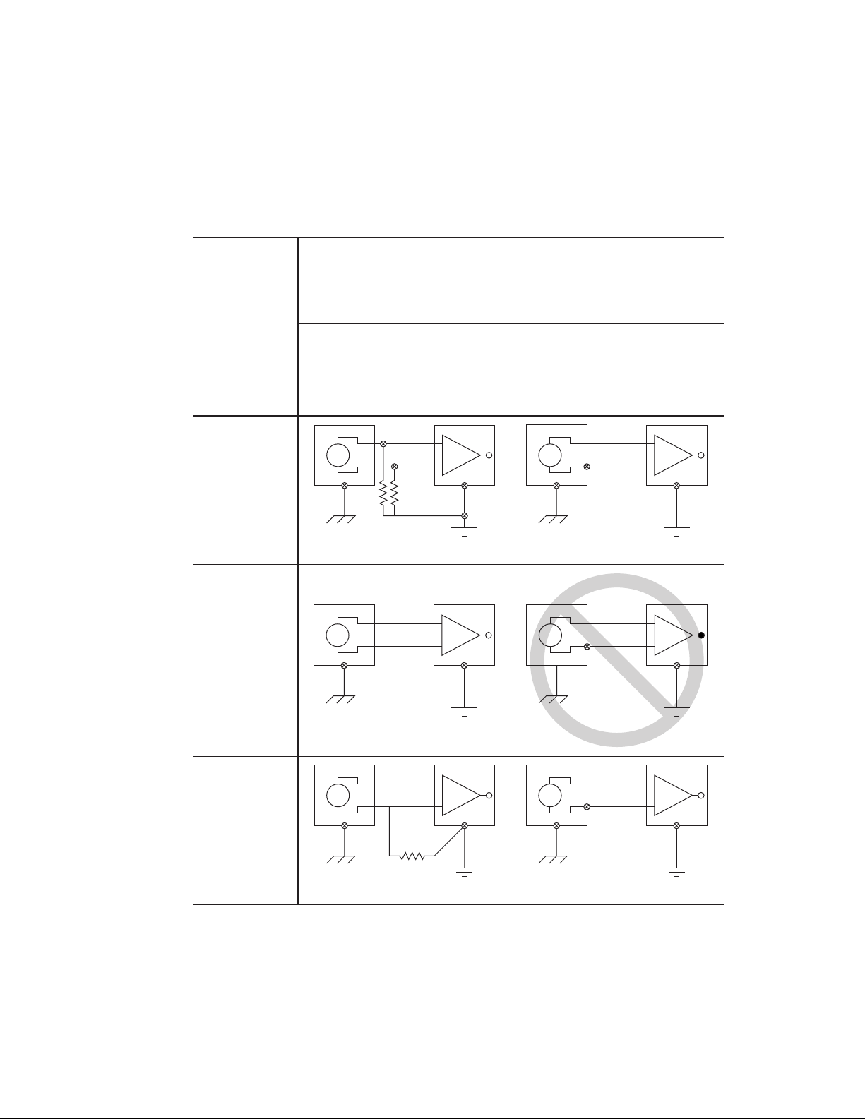
Figure 2-5 summarizes the recommended input mode for both types of
signal sources.
Figure 2-5. Summary of Analog Input Connections
+
–
+
–
V
1
AI<i>
AISENSE
AIGND<i>
+
–
+
–
V
1
AI<i>
AISENSE
AIGND<i>
See text for information on bias resistors.
+
–
+
–
V
1
AI<i>
AIGND<i>
+
–
+
–
V
1
AI
+ V
g
–
AIGND
Ground-loop losses, V
g
, are added to
measured signal.
NOT RECOMMENDED
+
–
+
–
V
1
AI<i>(+)
AI<i>(–)
AIGND<i>
+
–
+
–
V
1
AI<i>(+)
AI<i>(–)
AIGND<i>
See text for information on bias resistors.
Signal Source Type
Floating Signal Source
(Not Connected to Building Ground)
Grounded Signal Source
Examples
• Ungrounded Thermocouples
• Signal Conditioning with
Isolated Outputs
• Battery Devices
Examples
• Plug-in Instruments with
Nonisolated Outputs
Input
Differential
(DIFF)
Single-Ended—
Ground
Referenced
(RSE)
Single-Ended—
Nonreferenced
(NRSE)

Chapter 2 Hardware Overview of the NI 78xx
Multifunction Reconfigurable I/O User Manual 2-10 ni.com
Differential Connection Considerations (DIFF Input Mode)
In DIFF input mode, the NI 783x/784x/785x device measures the
difference between the positive and negative inputs. DIFF input mode is
ideal for measuring ground-referenced signals from other devices. When
using DIFF input mode, the input signal connects to the positive input of
the instrumentation amplifier and its reference signal, or return, connects to
the negative input of the instrumentation amplifier.
Use differential input connections for any channel that meets any of the
following conditions:
• The input signal is low level (less than 1 V).
• The leads connecting the signal to the device are greater than
3m(10ft).
• The input signal requires a separate ground-reference point or return
signal.
• The signal leads travel through noisy environments.
Differential signal connections reduce noise pickup and increase
common-mode noise rejection. Differential signal connections also
allow input signals to float within the common-mode limits of the
instrumentation amplifier.
Chapter 2 Hardware Overview of the NI 78xx
© National Instruments Corporation 2-11 Multifunction Reconfigurable I/O User Manual
Differential Connections for Ground-Referenced
Signal Sources
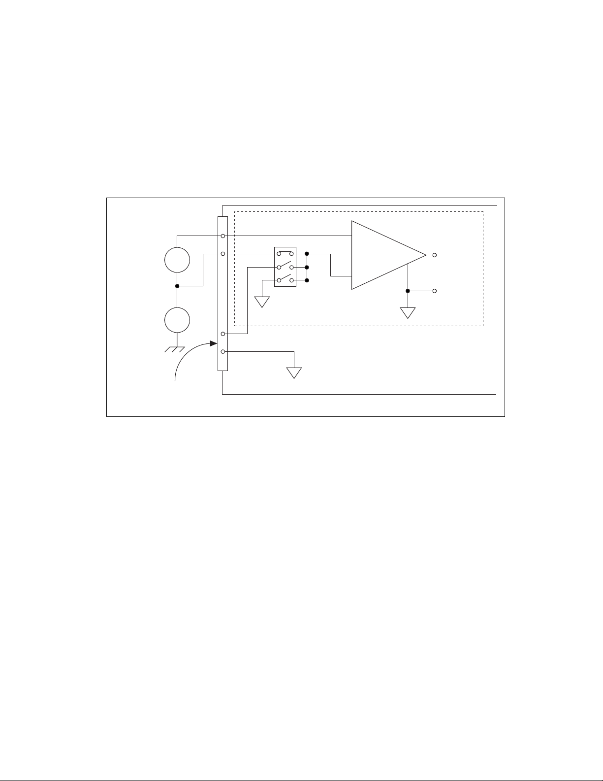
Figure 2-6 shows how to connect a ground-referenced signal source to a
channel on the NI 783x/784x/785x configured in DIFF input mode.
Figure 2-6. Differential Input Connections for Ground-Referenced Signals
With this connection type, the instrumentation amplifier rejects both the
common-mode noise in the signal and the ground potential difference
between the signal source and the NI 783x/784x/785x ground, shown as
V
cm
in Figure 2-6. In addition, the instrumentation amplifier can reject
common-mode noise pickup in the leads connecting the signal sources to
the device. The instrumentation amplifier can reject common-mode signals
when V+
in
and V–
in
(input signals) are both within their specified input
ranges. Refer to the Multifunction Reconfigurable I/O Specifications,
available at
ni.com/docs, for more information about input ranges.
DIFF Input Mode Selected
–
+
–
+
–
+
–
+
V
cm
V
s
I/O Connector
AISENSE
AIGND
V
m
AI+
AI–
Ground-
Referenced
Signal
Source
Common-
Mode
Noise and
Ground
Potential
Measured
Voltage
Instrumentation
Amplifier