multifunction-rio-user-manual.pdf - 第24页
Chapter 2 Hardware Overv iew of the NI 78x x Multifunction Reconfigur able I/O User Manual 2-6 ni.com eight AI channels of the NI 783 x /784 x /785 x . For all input modes, the AI<0.. n >+ signals are connected to …
Chapter 2 Hardware Overview of the NI 78xx
© National Instruments Corporation 2-5 Multifunction Reconfigurable I/O User Manual
Input Modes
The NI 783x/784x/785x input mode is software configurable. The input
channels support three input modes—differential (DIFF), referenced single
ended (RSE), and nonreferenced single ended (NRSE). The selected input
mode applies to all the input channels. Table 2-2 describes the three input
modes.
Input Range
The NI 783x/784x/785x AI range is fixed at ±10 V.
Connecting Analog Input Signals
The AI signals for the NI 783x/784x/785x are AI<0..n>+, AI<0..n>–,
AIGND, and AISENSE. For the NI 7830, n=4. For the NI 7831/7833/
784x/785x, n=8. The AI<0..n>+ and AI<0..n>– signals are connected to the
Negative full-scale range –10.000000 8000
Any input voltage —
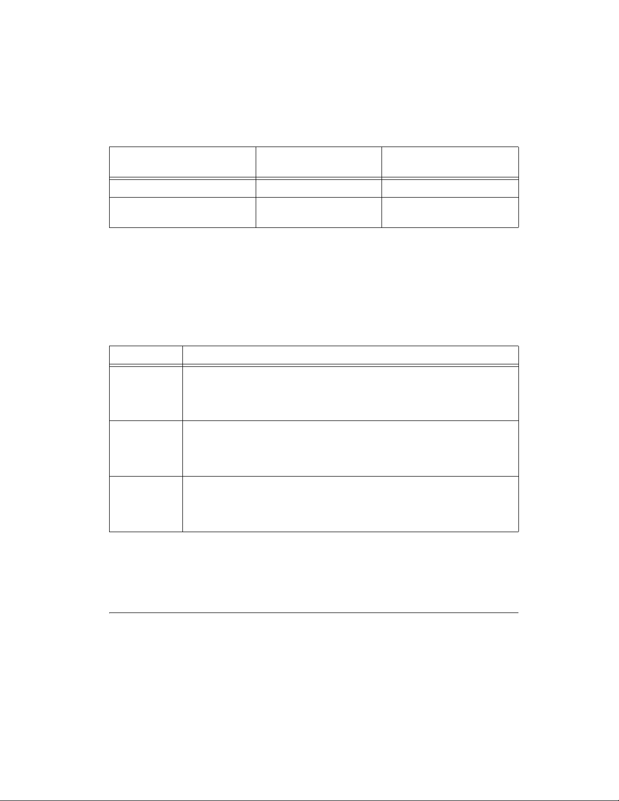
Table 2-2. Available Input Modes for the NI 783x/784x/785x
Input Mode Description
DIFF When the NI 783x/784x/785x is configured in DIFF input mode, each channel
uses two AI lines. The positive input pin connects to the positive terminal of the
onboard instrumentation amplifier. The negative input pin connects to the
negative input of the instrumentation amplifier.
RSE When the NI 783x/784x/785x is configured in RSE input mode, each channel
uses only its positive AI pin. This pin connects to the positive terminal of the
onboard instrumentation amplifier. The negative input of the instrumentation
amplifier connects internally to the AI ground (AIGND).
NRSE When the NI 783x/784x/785x is configured in NRSE input mode, each channel
uses only its positive AI pin. This pin connects to the positive terminal of the
onboard instrumentation amplifier. The negative input of the instrumentation
amplifier on each AI channel connects internally to the AISENSE input pin.
Table 2-1. Ideal Output Code and AI Voltage Mapping (Continued)
Input Description AI Voltage
Output Code (Hex)
(Two’s Complement)
Output Code
32,768
----------------------------------
10.0 V×

Chapter 2 Hardware Overview of the NI 78xx
Multifunction Reconfigurable I/O User Manual 2-6 ni.com
eight AI channels of the NI 783x/784x/785x. For all input modes, the
AI<0..n>+ signals are connected to the positive input of the
instrumentation amplifier on each channel. The signal connected to the
negative input of the instrumentation amplifier depends on how you
configure the input mode of the device.
In differential input mode, signals connected to AI<0..n>– are routed to the
negative input of the instrumentation amplifier for each channel. In RSE
input mode, the negative input of the instrumentation amplifier for each
channel is internally connected to AIGND. In NRSE input mode, the
AISENSE signal is connected internally to the negative input of the
instrumentation amplifier for each channel. In DIFF and RSE input modes,
AISENSE is not used.
Caution Exceeding the differential and common-mode input ranges distorts the
input signals. Exceeding the maximum input voltage rating can damage the
NI 783x/784x/785x and the computer. NI is not liable for any damage resulting from such
signal connections. The maximum input voltage ratings are listed in Table A-2, NI 78xx
I/O Signal Summary.
AIGND is a common AI signal that is routed directly to the ground tie point
on the NI 783x/784x/785x. You can use this signal for a general analog
ground tie point to the device if necessary.
Chapter 2 Hardware Overview of the NI 78xx
© National Instruments Corporation 2-7 Multifunction Reconfigurable I/O User Manual
Connection of AI signals to the NI 783x/784x/785x depends on the input
mode of the AI channels you are using and the type of input signal source.
With different input modes, you can use the instrumentation amplifier in
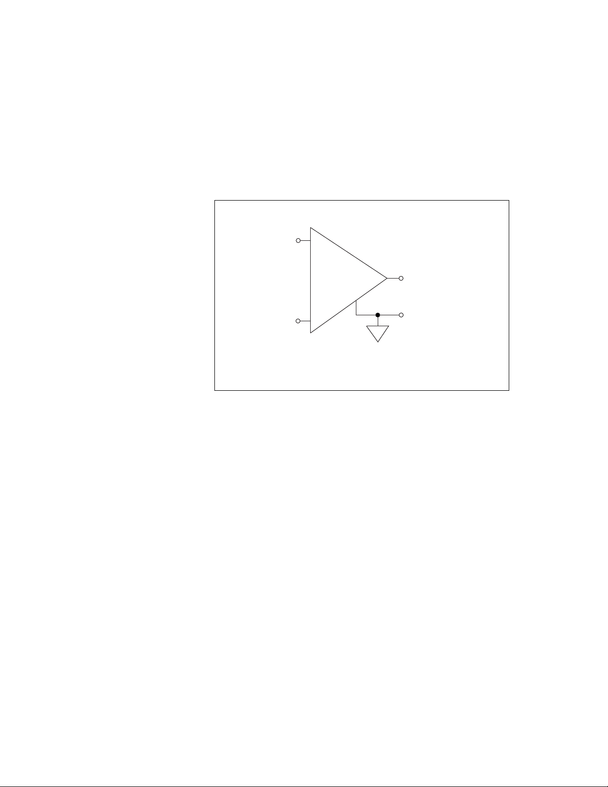
different ways. Figure 2-4 shows a diagram of the device instrumentation
amplifier.
Figure 2-4. NI 783x/784x/785x Instrumentation Amplifier
The instrumentation amplifier applies common-mode voltage rejection
and presents high input impedance to the AI signals connected to the
NI 783x/784x/785x. Input multiplexers on the device route signals to the
positive and negative inputs of the instrumentation amplifier. The
instrumentation amplifier converts two input signals to a signal that is the
difference between the two input signals. The amplifier output voltage is
referenced to the device ground. The device ADC measures this output
voltage when it performs A/D conversions.
You must reference all signals to ground either at the source device or at the
NI 783x/784x/785x. If you have a floating source, reference the signal to
ground by using RSE input mode or the DIFF input mode with bias
resistors. Refer to the Differential Connections for Nonreferenced or
Floating Signal Sources section of this chapter for more information about
these input modes. If you have a grounded source, do not reference the
signal to AIGND. You can avoid this reference by using DIFF or NRSE
input modes.
+
+
–
–
V
m
= [V
in+
– V
in–
]
V
in+
V
in–
V
m
Instrumentation
Amplifier
Measured
Voltage