multifunction-rio-user-manual.pdf - 第54页
Appendix A Connecting I/O Signals Multifunction Reconfigur able I/O User Manual A-4 ni.com T o access the signals on the I/O connect ors, you must connect a cable from the I/O connector to a signal acces sory . Plug the …
Appendix A Connecting I/O Signals
© National Instruments Corporation A-3 Multifunction Reconfigurable I/O User Manual
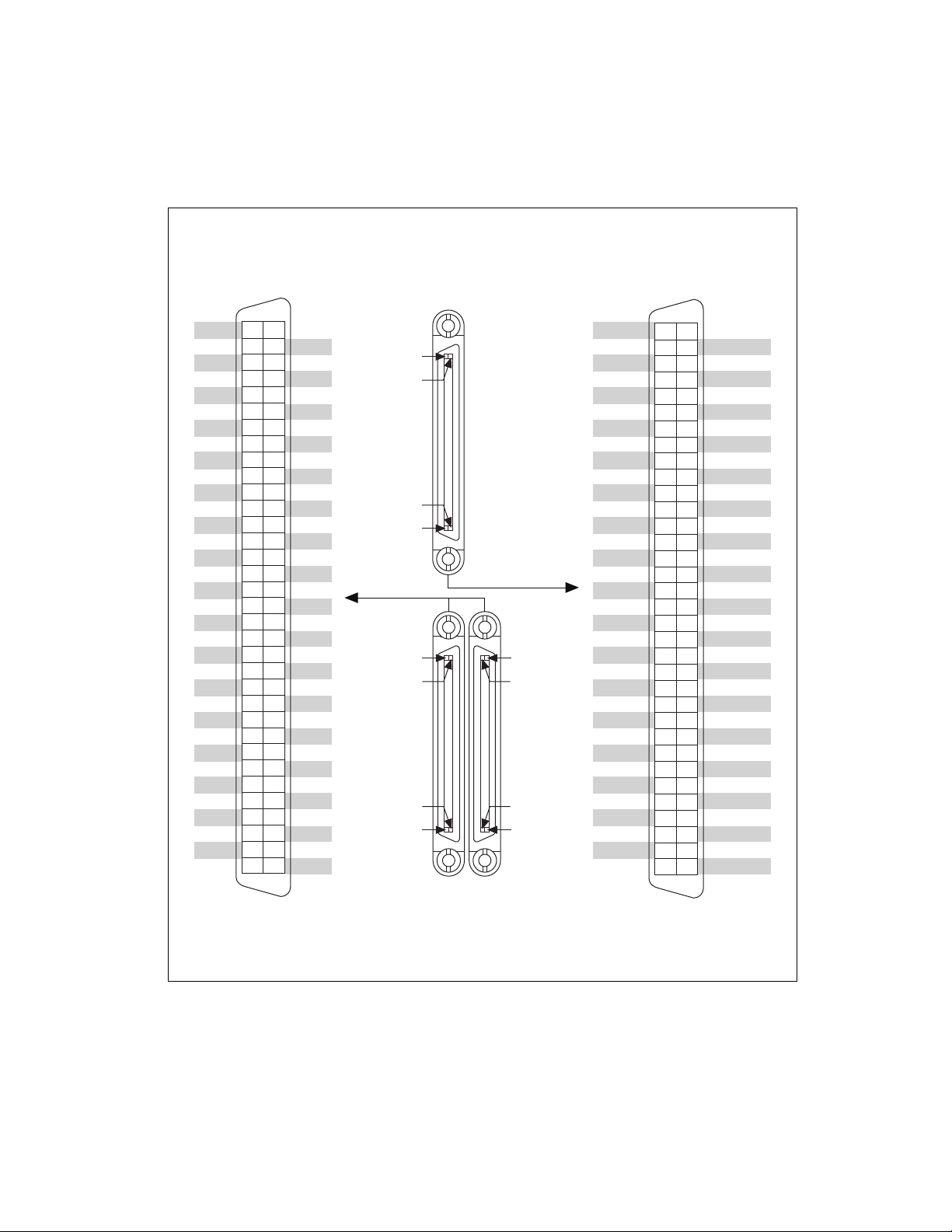
Figure A-2. NI 783x/784x/785x Connector Pin Assignments and Locations
+5V
DGND
DGND
DGND
DGND
DGND
DGND
DGND
DGND
DIO8
DIO10
DIO12
DIO14
AOGND7
AOGND6
AOGND5
AOGND4
AOGND3
AOGND2
AOGND1
AOGND0
No Connect
AI7–
1
AIGND7
AI6–
1
AI5–
1
AIGND5
AI4–
1
AI3–
AIGND3
AI2–
AI1–
AIGND1
AI0–
+5V
DIO1
DIO2
DIO4
DIO5
DIO6
DIO7
DIO0
DIO3
DIO9
DIO11
DIO13
DIO15
AO7
1
AO6
1
AO5
1
AO4
1
AO3
AO2
AO1
AO0
AISENSE
AI7+
1
AIGND6
AI6+
1
AI5+
1
AIGND4
AI4+
1
AI3+
AIGND2
AI2+
AI1+
AIGND0
AI0+
35 1
36 2
37 3
38 4
39 5
40 6
41 7
42 8
43 9
44 10
45 11
46 12
47 13
48 14
49 15
50 16
51 17
52 18
53 19
54 20
55 21
56 22
57 23
58 24
59 25
60 26
61 27
62 28
63 29
64 30
65 31
66 32
67 33
68 34
1
No Connect on the NI 7830
DGND
DGND
DGND
DGND
DGND
DGND
DGND
DGND
DGND
DGND
DGND
DGND
DGND
DGND
DGND
DGND
DGND
DGND
DGND
DGND
DGND
DGND
DGND
DGND
DGND
DGND
+5V
+5V
DIO28
DIO31
DIO33
DIO35
DIO37
DIO39
DIO0
DIO2
DIO3
DIO5
DIO6
DIO7
DIO8
DIO1
DIO4
DIO9
DIO10
DIO11
DIO12
DIO13
DIO14
DIO15
DIO16
DIO17
DIO18
DIO19
DIO20
DIO21
DIO22
DIO23
DIO24
DIO25
DIO26
DIO27
DIO29
DIO30
DIO32
DIO34
DIO36
DIO38
35 1
36 2
37 3
38 4
39 5
40 6
41 7
42 8
43 9
44 10
45 11
46 12
47 13
48 14
49 15
50 16
51 17
52 18
53 19
54 20
55 21
56 22
57 23
58 24
59 25
60 26
61 27
62 28
63 29
64 30
65 31
66 32
67 33
68 34
CONNECTOR 1
(RDIO)
TERMINAL 34
TERMINAL 68
TERMINAL 35
TERMINAL 1
TERMINAL 35
TERMINAL 1
TERMINAL 34
TERMINAL 68
TERMINAL 34
TERMINAL 68
TERMINAL 35
TERMINAL 1
CONNECTOR 0
(RMIO)
CONNECTOR 2
(RDIO)
Appendix A Connecting I/O Signals
Multifunction Reconfigurable I/O User Manual A-4 ni.com
To access the signals on the I/O connectors, you must connect a cable from
the I/O connector to a signal accessory. Plug the small VHDCI connector
end of the cable into the appropriate I/O connector and connect the other
end of the cable to the appropriate signal accessory.
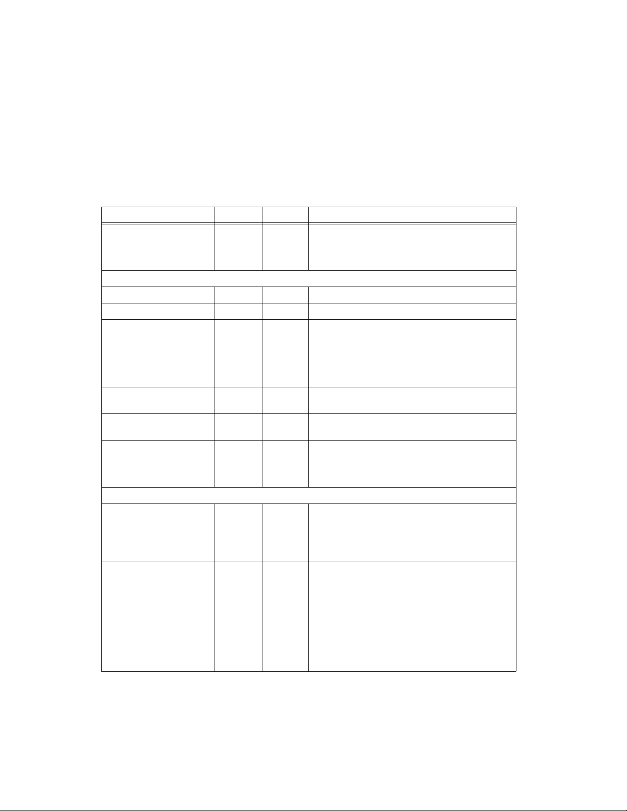
Table A-1. I/O Connector Signal Descriptions
Signal Name Reference Direction Description
+5V DGND Output +5 VDC Source—These pins supply 5 V from the computer
power supply. For more information on the +5V terminals,
refer to the +5 V Power Source section in Chapter 2,
Hardware Overview of the NI 78xx.
Analog Signals (NI 783x/784x/785x Only)
AI<0..7>+ AIGND Input Positive input for Analog Input channels 0 through 7.
AI<0..7>– AIGND Input Negative input for Analog Input channels 0 through 7.
AIGND — — Analog Input Ground—These pins are the reference point
for single-ended measurements in RSE configuration and
the bias current return point for differential measurements.
All three ground references—AIGND, AOGND, and
DGND—are connected to each other on the
NI 783x/784x/785x.
AISENSE AIGND Input Analog Input Sense—This pin serves as the reference node
for AI <0..7> when the device is configured for NRSE mode.
AO<0..7> AOGND Output Analog Output channels 0 through 7. Each channel can
source or sink up to 2.5 mA.
AOGND — — Analog Output Ground—The analog output voltages
are referenced to this node. All three ground
references—AIGND, AOGND, and DGND—are
connected to each other on the NI 783x/784x/785x.
Digital Signals (All NI 78xx Devices)
DGND — — Digital Ground—These pins supply the reference for the
digital signals at the I/O connector and the 5 V supply.
All three ground references—AIGND, AOGND, and
DGND—are connected to each other on the
NI 783x/784x/785x.
DIO<0..39>
Connector <0..3>
(NI 781x)
DIO<0..15>
Connector 0
(NI 783x/784x/785x)
DIO<0..39>
Connector <1..2>
(NI 783x/784x/785x)
DGND Input or
Output
Digital I/O signals.
Appendix A Connecting I/O Signals
© National Instruments Corporation A-5 Multifunction Reconfigurable I/O User Manual
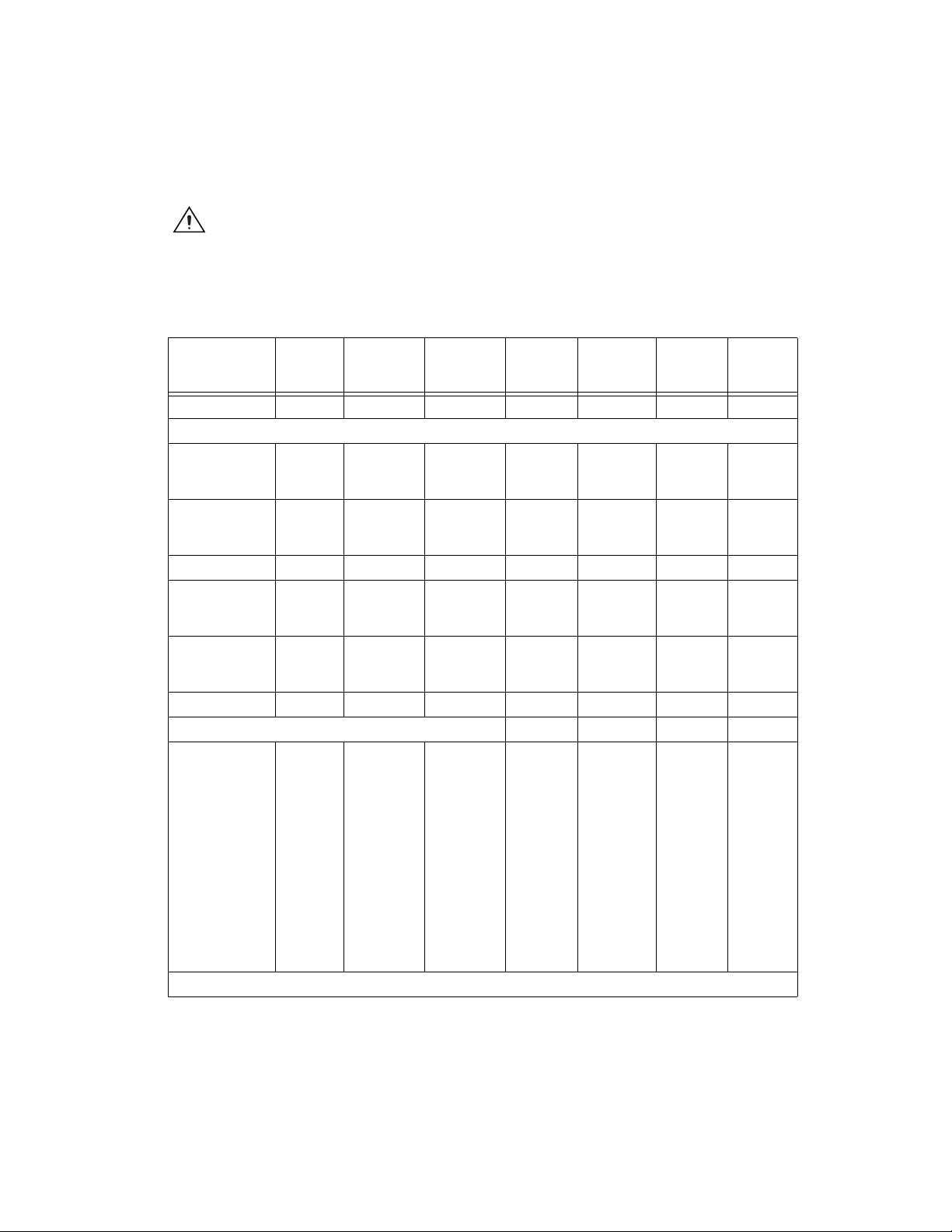
Caution Connections that exceed any of the maximum ratings of input or output signals
on the NI 78xx can damage the NI 78xx and the computer. Maximum input ratings for each
signal are in the Protection column of Table A-2. NI is not liable for any damage resulting
from such signal connections
Table A-2. NI 78xx I/O Signal Summary
Signal Name
Signal
Type and
Direction
Impedance
Input/
Output
Protection
(Volts)
On/Off
Source
(mA at V)
Sink
(mA at V)
Rise Time Bias
+5V DO — — — — — —
Analog Signals (NI 783x/784x/785x Only)
AI<0..7>+ AI 10 GΩ in
parallel with
100 pF
42/35 — — — ±2 nA
AI<0..7>– AI 10 GΩ in
parallel with
100 pF
42/35 — — — ±2 nA
AIGND AO — — — — — —
AISENSE AI 10 GΩ in
parallel with
100 pF
42/35 — — — ±2 nA
AO<0..7> AO 1.25 Ω Short
circuit to
ground
2.5 at 10 2.5 at –10 10 V/μs —
AOGND AO — — — — — —
Digital Signals (All NI 78xx Devices) — — — —
DIO<0..39>
Connector <0..3>
(NI 781x)
DIO<0..15>
Connector 0
(NI 783x,
NI 784x, and
NI 785x)
DIO<0..39>
Connector <1..2>
(NI 783x,
NI 784x, and
NI 785x)
DIO — –0.5 to +7.0
(NI 783x)
–20 to 20
(NI 784x/
NI 785x)
4.0 at 2.4 4.0 at 0.4 — —
AI = Analog Input AO = Analog Output DIO = Digital Input/Output DO = Digital Output