multifunction-rio-user-manual.pdf - 第44页
Chapter 2 Hardware Overv iew of the NI 78x x Multifunction Reconfigurable I/O U ser Manual 2-26 ni.com Figure 2-17. Switch Settings Complete the following steps to prevent a VI stored in Flash me mory from loading to the…
Chapter 2 Hardware Overview of the NI 78xx
© National Instruments Corporation 2-25 Multifunction Reconfigurable I/O User Manual
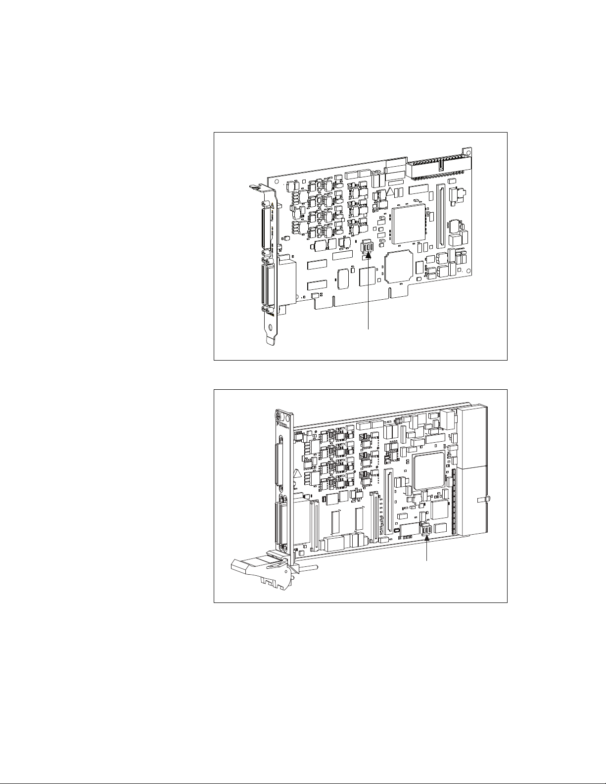
Figure 2-15. Switch Location on the PCI-783x
Figure 2-16. Switch Location on the PXI-783x
SW1, SW2, SW3
SW1, SW2, SW3
CONNECTOR 2 (DIO)
NI PXI-7831R
Reconfigurable I/O
Chapter 2 Hardware Overview of the NI 78xx
Multifunction Reconfigurable I/O User Manual 2-26 ni.com
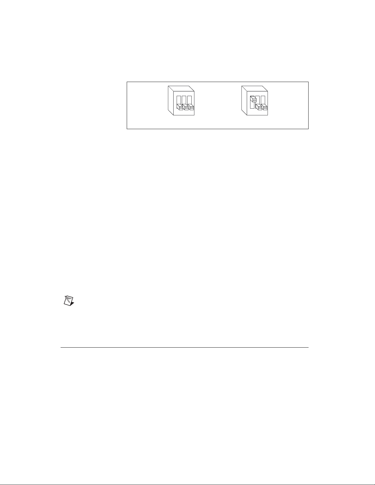
Figure 2-17. Switch Settings
Complete the following steps to prevent a VI stored in Flash memory from
loading to the FPGA:
1. Power off and unplug the PXI/CompactPCI chassis or PCI computer.
2. Remove the NI 781x/783x from the PXI/CompactPCI chassis or PCI
computer.
3. Move SW1 to the ON position, as shown in Figure 2-17b.
4. Reinsert the NI 781x/783x into the PXI/CompactPCI chassis or PCI
computer. Refer to the Installing the Hardware section of the Getting
Started with R Series Multifunction RIO document for installation
instructions.
5. Plug in and power on the PXI/CompactPCI chassis or PCI computer.
After completing this procedure, a VI stored in Flash memory does not load
to the FPGA at power-on. You can use software to configure the NI 78xx,
if necessary. To return to the defaults of loading from Flash memory, repeat
the previous procedure but return SW1 to the OFF position in step 3. You
can use this switch to enable/disable the ability to load from Flash memory.
In addition to this switch, you must configure the NI 78xx with the software
to autoload an FPGA VI.
Note When the NI 781x/783x is powered on with SW1 in the ON position, the analog
circuitry does not return properly calibrated data. Move the switch to the ON position only
while you are using software to reconfigure the NI 781x/783x for the desired power-up
behavior. Afterward, return SW1 to the OFF position.
+5 V Power Source
The +5 V terminals on the I/O connector supply +5 V referenced to DGND.
Use these terminals to power external circuitry.
Newer revision NI 781x/783x devices have a traditional fuse to protect the
supply from overcurrent conditions. This fuse is not customer-replaceable;
if the fuse permanently opens, return the device to NI for repair.
123
ON
123
ON
a. Normal Operation (Default) b. Prevent VI From Loading

Chapter 2 Hardware Overview of the NI 78xx
© National Instruments Corporation 2-27 Multifunction Reconfigurable I/O User Manual
Older revision NI 781x/783x devices have a self-resetting fuse to protect
the supply from overcurrent conditions. This fuse resets automatically
within a few seconds after the overcurrent condition is removed. For more
information about the self-resetting fuse and precautions to take to
avoid improper connection of +5 V and ground terminals, refer to the
KnowledgeBase document, Self-Resetting Fuse Additional Information,
by going to
ni.com/info and entering the info code pptc.
(NI 784x /785x Devices) All NI 784x/785x devices have a user-replaceable
socketed fuse to protect the supply from overcurrent conditions. When an
overcurrent condition occurs, check your cabling to the +5 V terminals and
replace the fuse as described in the Device Fuse Replacement (NI
784x/785x Only) section.
Caution Never connect the +5 V power terminals to analog or digital ground or to any
other voltage source on the NI 78xx device or any other device. Doing so can damage the
device and the computer. NI is not liable for damage resulting from such a connection.
The power rating on most devices is +4.75 to +5.25 VDC at 1 A.
Refer to the Multifunction Reconfigurable I/O Specifications document,
available at
ni.com/docs, to obtain the power rating for your device.
Device Fuse Replacement (NI 784x /785x Only)
NI 784x/785x devices have a replaceable fuse, Littelfuse part
number 0453004, that protects the device from overcurrent through
the power connector.
To replace a blown fuse in the NI 784x/785x, complete the following steps:
1. Power down and unplug the computer or PXI chassis.
2. Remove the PCI/PCI Express device from the expansion slot on the
computer, or the PXI device from the PXI slot in the PXI chassis.