multifunction-rio-user-manual.pdf - 第27页
Chapter 2 Hardware Overview of the NI 78x x © National Instruments Corporation 2-9 Mult ifunction Reconfigurable I/O User Manual Figure 2-5 summarizes the recommended in put mode for both type s of signal sources. Figure…

Chapter 2 Hardware Overview of the NI 78xx
Multifunction Reconfigurable I/O User Manual 2-8 ni.com
Types of Signal Sources
When configuring the input channels and making signal connections,
you must first determine whether the signal sources are floating or ground
referenced. The following sections describe these two signal types.
Floating Signal Sources
A floating signal source is not connected to the building ground system but
instead has an isolated ground-reference point. Some examples of floating
signal sources are outputs of transformers, thermocouples, battery-powered
devices, optical isolator outputs, and isolation amplifiers. An instrument
or device that has an isolated output is a floating signal source.
You must connect the ground reference of a floating signal to the
NI 783x/784x/785x AIGND through a bias resistor to establish a local or
onboard reference for the signal. Otherwise, the measured input signal
varies as the source floats out of the common-mode input range.
Ground-Referenced Signal Sources
A ground-referenced signal source is connected to the building system
ground, so it is already connected to a common ground point with respect
to the NI 783x/784x/785x, assuming that the computer is plugged into the
same power system. Instruments or devices with nonisolated outputs that
plug into the building power system are ground referenced signal sources.
The difference in ground potential between two instruments connected to
the same building power system is typically between 1 and 100 mV. This
difference can be much higher if power distribution circuits are improperly
connected. If a grounded signal source is improperly measured, this
difference might appear as a measurement error. The connection
instructions for grounded signal sources are designed to eliminate this
ground potential difference from the measured signal.
Input Modes
The following sections discuss single-ended and differential measurements
and considerations for measuring both floating and ground-referenced
signal sources.
Chapter 2 Hardware Overview of the NI 78xx
© National Instruments Corporation 2-9 Multifunction Reconfigurable I/O User Manual
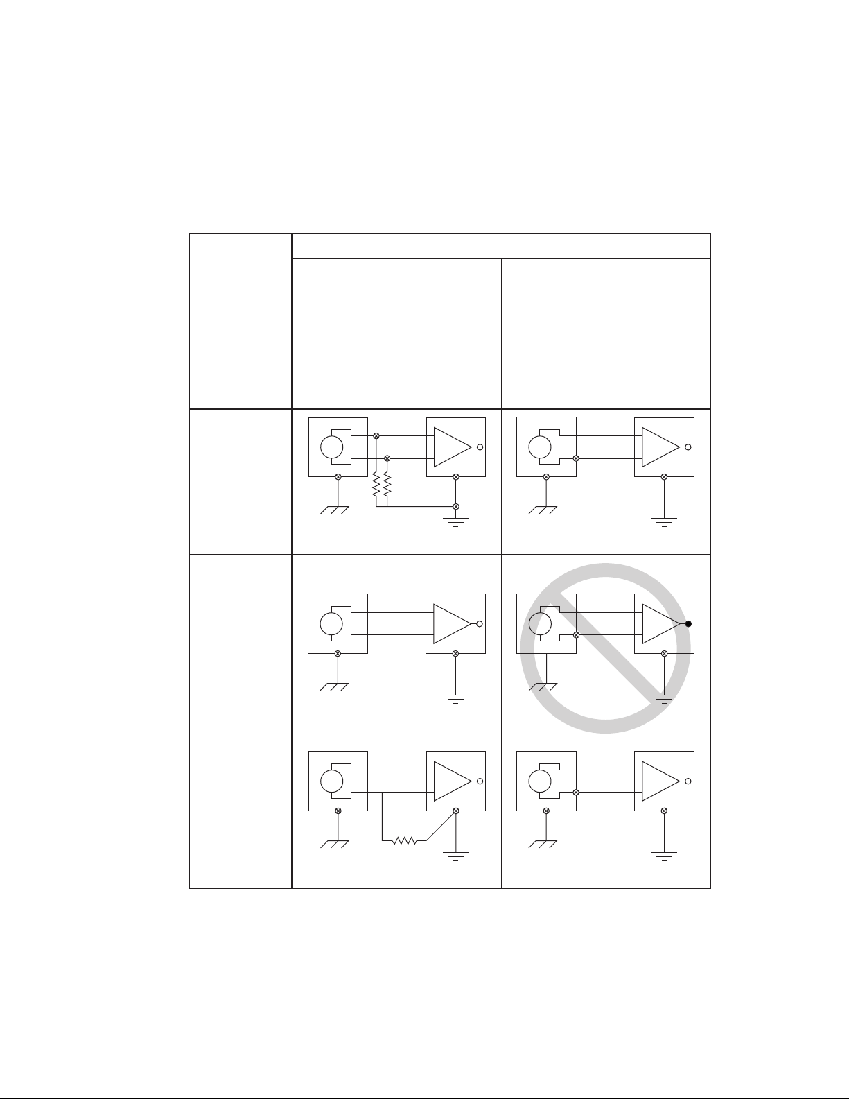
Figure 2-5 summarizes the recommended input mode for both types of
signal sources.
Figure 2-5. Summary of Analog Input Connections
+
–
+
–
V
1
AI<i>
AISENSE
AIGND<i>
+
–
+
–
V
1
AI<i>
AISENSE
AIGND<i>
See text for information on bias resistors.
+
–
+
–
V
1
AI<i>
AIGND<i>
+
–
+
–
V
1
AI
+ V
g
–
AIGND
Ground-loop losses, V
g
, are added to
measured signal.
NOT RECOMMENDED
+
–
+
–
V
1
AI<i>(+)
AI<i>(–)
AIGND<i>
+
–
+
–
V
1
AI<i>(+)
AI<i>(–)
AIGND<i>
See text for information on bias resistors.
Signal Source Type
Floating Signal Source
(Not Connected to Building Ground)
Grounded Signal Source
Examples
• Ungrounded Thermocouples
• Signal Conditioning with
Isolated Outputs
• Battery Devices
Examples
• Plug-in Instruments with
Nonisolated Outputs
Input
Differential
(DIFF)
Single-Ended—
Ground
Referenced
(RSE)
Single-Ended—
Nonreferenced
(NRSE)

Chapter 2 Hardware Overview of the NI 78xx
Multifunction Reconfigurable I/O User Manual 2-10 ni.com
Differential Connection Considerations (DIFF Input Mode)
In DIFF input mode, the NI 783x/784x/785x device measures the
difference between the positive and negative inputs. DIFF input mode is
ideal for measuring ground-referenced signals from other devices. When
using DIFF input mode, the input signal connects to the positive input of
the instrumentation amplifier and its reference signal, or return, connects to
the negative input of the instrumentation amplifier.
Use differential input connections for any channel that meets any of the
following conditions:
• The input signal is low level (less than 1 V).
• The leads connecting the signal to the device are greater than
3m(10ft).
• The input signal requires a separate ground-reference point or return
signal.
• The signal leads travel through noisy environments.
Differential signal connections reduce noise pickup and increase
common-mode noise rejection. Differential signal connections also
allow input signals to float within the common-mode limits of the
instrumentation amplifier.