Workcell-Installation-Guidelines-Troubleshooting-Maintenance-REV-F.pdf - 第15页
Workcell Installation and General Guidelines Revision F / Janu ary 2021 Page 15 of 59 Board Sensor Sensitivi ty Adjustment Proce dures Board sensors are optic sensors that face upw ard along the le ngth of the front of t…
Workcell Installation and General Guidelines
Revision F / January 2021
Page 14 of 59
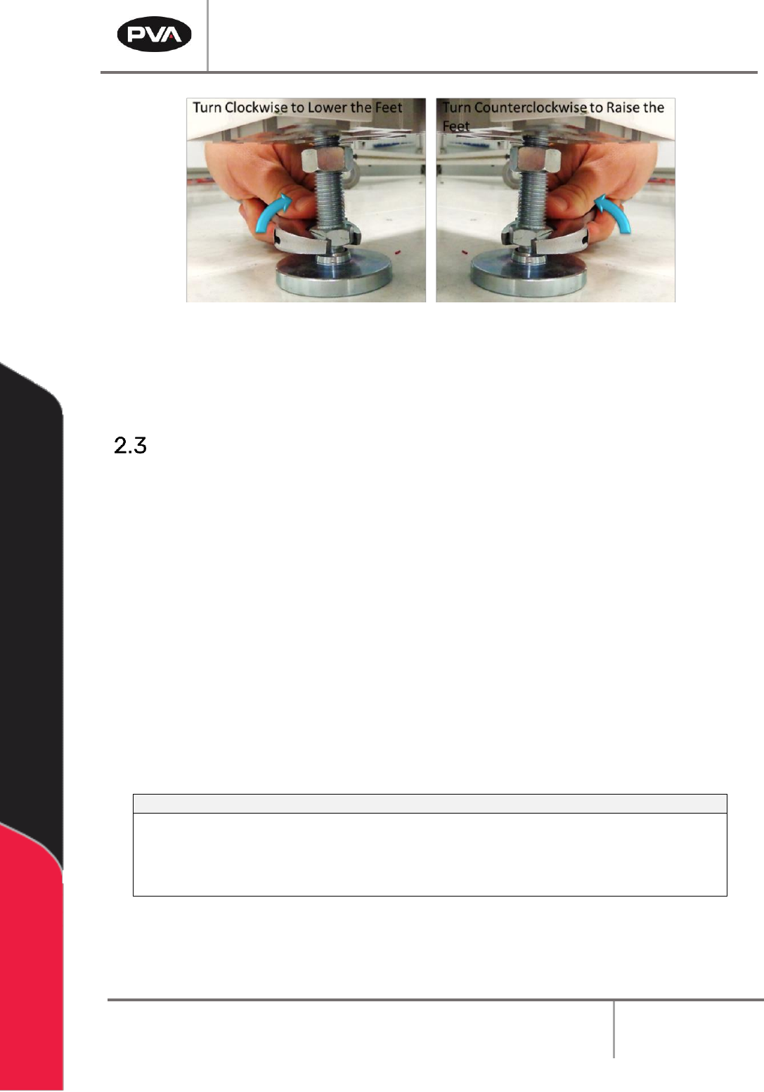
Figure 3: Adjust the Feet
6. Gently lower the workcell and remove the forklift. It is not necessary to tighten the
lock nuts at this time.
Light Tower Operation
Three stacked indicator lights and a buzzer are used to show the machine status. The
lights are green, amber, and red and can be seen from all sides of the machine. The buzzer
is below the green light. The lights and buzzer operate as follows:
• The green light is on when the machine is in cycle and parts are made. It is off at all
other times.
• The amber light is on when the machine is in Auto Cycle and ready to make parts, but
cannot cycle because the workcell is waiting for another machine or there is an
external material handling problem (no incoming parts or no room to unload parts).
• The red light is on steady when the machine is not in Auto Cycle. It will flash when the
workcell is in an error state.
• The buzzer operates with the red light during machine errors.
212B244BState
213B245BRed
214B246BAmber
215B247BGreen
216B248BBuzzer
217B249BCycle Stop
218B250BON
219B251BOFF
220B252BOFF
221B253BOFF
222B254BAuto Cycle
223B255BOFF
224B256BON
225B257BOFF
226B258BOFF
227B259BIn Cycle
228B260BOFF
229B261BOFF
230B262BON
231B263BOFF
232B264BMachine Error
233B265BFLASH
234B266BOFF
235B267BOFF
236B268BFLASH
Figure 4: Light Tower & Buzzer Status
Note: This is the standard configuration. Actual configuration depends on the
workcell.
Workcell Installation and General Guidelines
Revision F / January 2021
Page 15 of 59
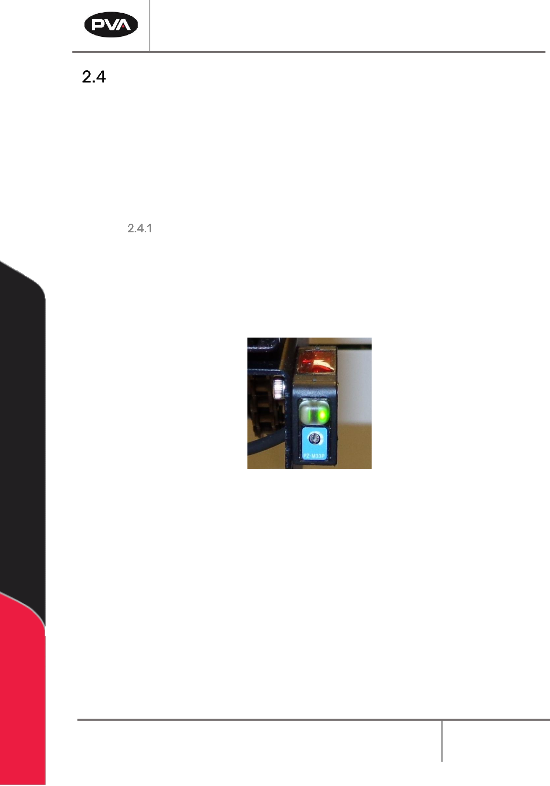
Board Sensor Sensitivity Adjustment Procedures
Board sensors are optic sensors that face upward along the length of the front of the
conveyors. They detect the presence of a part and send a signal to the motion controller. If
a board is reflective or shiny, or does not process correctly adjust the board sensors.
The number of sensors depends on your system, but your workcell may have up to five
board sensors. There can be one for each zone (entry zone, primary spray/work area, exit
zone, return work area, and part detection). Adjust each sensor as necessary.
To Adjust the Board Sensors
You will need a small flat head screwdriver and part or sample board to be processed.
1. Put a part on the conveyor’s rail and examine sensor sensitivity.
2. To increase sensitivity, use a small screwdriver to turn the sensor screw clockwise.
To decrease sensitivity turn the sensor screw counterclockwise.
Figure 5: Board Sensor
3. Use the sample part to examine the board sensors on both sides (top and bottom) of
the conveyors.
4. If only the green LED is on, the sensor is OFF. If the Orange LED is on the sensor is ON.
Workcell Installation and General Guidelines
Revision F / January 2021
Page 16 of 59
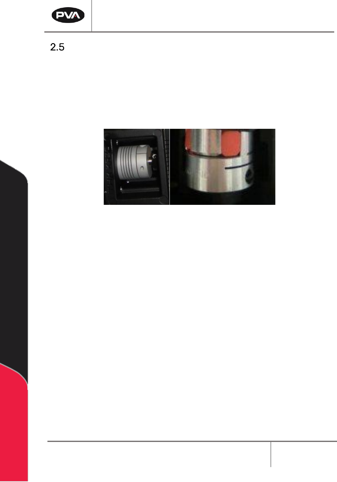
Servo Motor Couplings
Servo couplings are compensating couplings that are backlash free with conformal torque
transfer. They supply high torsion stiffness and a low moment of inertia. Examine the servo
motor couplings if shifting is suspected and to tighten the set screws.
Note: It may be necessary to remove the motor to get access to the second set
screw. The second set screw is not always visible but must also be tightened
periodically.
Figure 6: Servo Couplings