Workcell-Installation-Guidelines-Troubleshooting-Maintenance-REV-F.pdf - 第25页
Workcell Installation and General Guidelines Revision F / Janu ary 2021 Page 25 of 59 Exhaust F an Some machines h ave an optio na l exhaust fan to rem ove fumes f rom the work area. You must use th e exhaust fan if you …
Workcell Installation and General Guidelines
Revision F / January 2021
Page 24 of 59
Operating Safety
The workcell has several safety features that protect the operator from hazards in normal
machine operation.
Warning! The safety features should NEVER be bypassed, disabled, or tampered with.
PVA is not responsible for any damage, mechanical or human, caused by changes or
destruction of any safety features.
Safety Circuit
The main power to the workcell is monitored and controlled by the safety circuit. The
safety circuit contains two relays under-voltage protection and one or more safety
devices. The relays are wired in a redundant manner. The tripping contacts of the relays
are connected in series so the safety circuit will disconnect power even if one of the relays
fails. The relays are self-checking with positive guided contacts electrically forced to
operate together. If one redundant relays fails or a safety switch is activated, the power
contacts are opened.
Polycarbonate and Safety Glass Guarding
The work area is enclosed with either polycarbonate or safety glass guarding. The front of
the workcell is either open, for the manual processing of parts, or has doors.
Doors
Workcells with an automatic load/unload cycle will have one or two doors in the front. Each
door is monitored by a non-defeatable limit switch. When a door is opened, power to the
motors and pneumatics is disconnected. The DOOR BYPASS key switch is for maintenance
personnel to access the work area without disconnecting power. The bypass switch can
only be used in manual or calibration mode.
Light Curtain
Some workcells have a light curtain. The light curtain is redundant and self-checking. The
control signals from the light curtain are safety devices in the safety circuit.
Workcell Installation and General Guidelines
Revision F / January 2021
Page 25 of 59
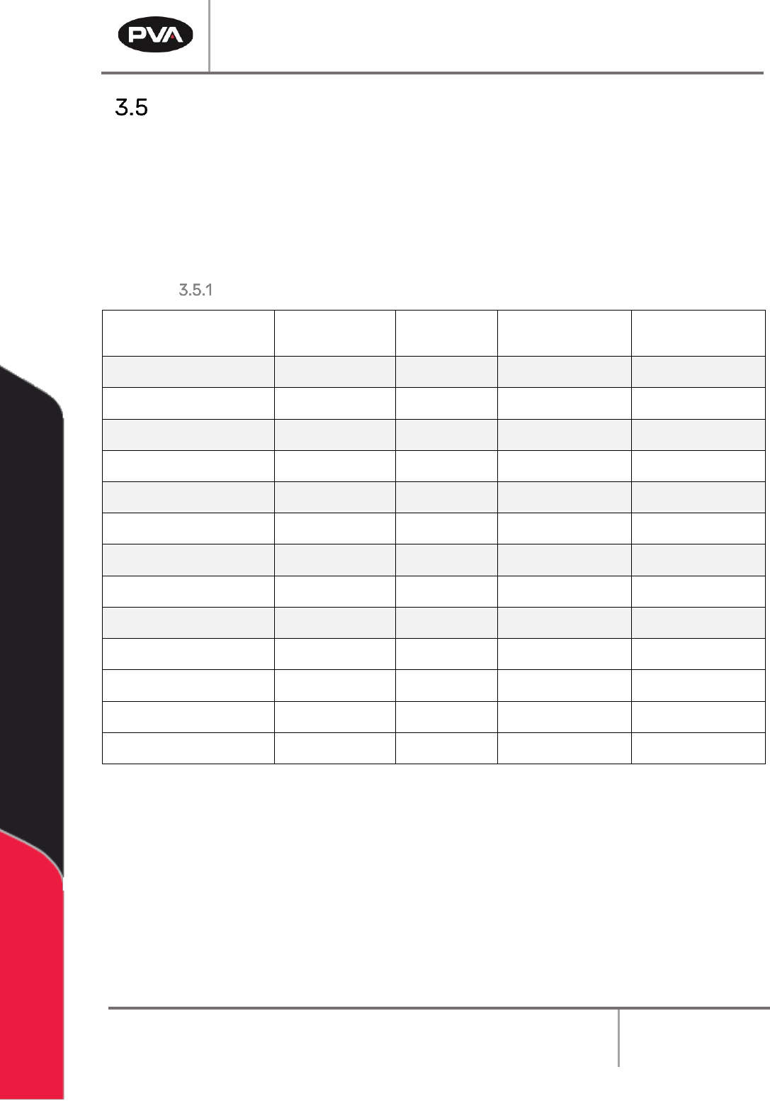
Exhaust Fan
Some machines have an optional exhaust fan to remove fumes from the work area. You
must use the exhaust fan if your workcell was designed with one. Please refer to the
workcell specifications for the specific necessary exhaust flow for your workcell. The
exhaust flange should be connected to a duct system that can receive the required* CFM
(cubic feet per minute) while maintaining less than 1.0” H
2
O static pressure in the duct. If
airflow through the exhaust system is not sufficient, it will generate an error.
Standard Machine Exhaust Requirements
Machine
Exhaust
Requirement
Machine
Duct Size
Air Velocity at
Test Point
(ft/min)
Air Velocity at
Test Point
(m/sec)
PVA350
300 CFM
4” (102mm)
3438
17.5
Delta 6
300 CFM
4” (102mm)
3438
17.5
Delta 8
300 CFM
4” (102mm)
3438
17.5
Flex Cell
Contact PVA
Varies
Varies
Varies
DeltaTherm 4’
200 CFM
4” (102mm)
2292
11.6
DeltaTherm 8’
300 CFM
6” (152mm)
1528
7.8
DeltaTherm 8’ H
140 CFM
6” (152mm)
713
3.6
DeltaTherm 12’
600 CFM
6” (152mm)
3056
15.5
DeltaTherm 12’ H
210 CFM
6” (152mm)
1070
5.4
DeltaTherm 16’
1000 CFM
6” (152mm)
5093
25.9
DeltaTherm 16’ H
280 CFM
6” (152mm)
1426
7.2
Spectra*
600 - 1200 CFM*
6” (152mm)
3056
15.5
Queue/Inspect Station
300 CFM
4” (102mm)
3438
17.5
*H denotes Humidity Option
*Spectra units that are double-sided have two exhaust ports and an exhaust requirement of 1200
CFM (600 CFM for each exhaust port).
Note: Check machine specifications. Custom order machines and processes may
require higher exhaust flow rates.
Note: Refer the Material Safety Data Sheets (MSDS) for safety precautions on any
chemicals used in PVA equipment.
Note: The safety devices on your workcell will be different with each model

Workcell Installation and General Guidelines
Revision F / January 2021
Page 26 of 59
Air Velocity Test Points
Delta 6, Delta 8, and Flex Cells
If there is no optional exhaust blower, measure the velocity at the port located inside the
workcell. The port is typically on the back wall or the horizontal deck pan inside the
machine. If an optional blower is present, measure the velocity at the inlet to the factory
supplied duct.
Figure 14: Measure Velocity at Port
DeltaTherm, Spectra, and Queue/Inspect Station
Measure the velocity at the inlet to the factory supplied duct.
Figure 15: Measure Velocity at Duct Inlet