Workcell-Installation-Guidelines-Troubleshooting-Maintenance-REV-F.pdf - 第20页
Workcell Installation and General Guidelines Revision F / Janu ary 2021 Page 20 of 59 Level th e Workcell This is the proc edure to lev el the workcell. If the workcell will be us ed as an in-line system, it needs to b e…
Workcell Installation and General Guidelines
Revision F / January 2021
Page 19 of 59
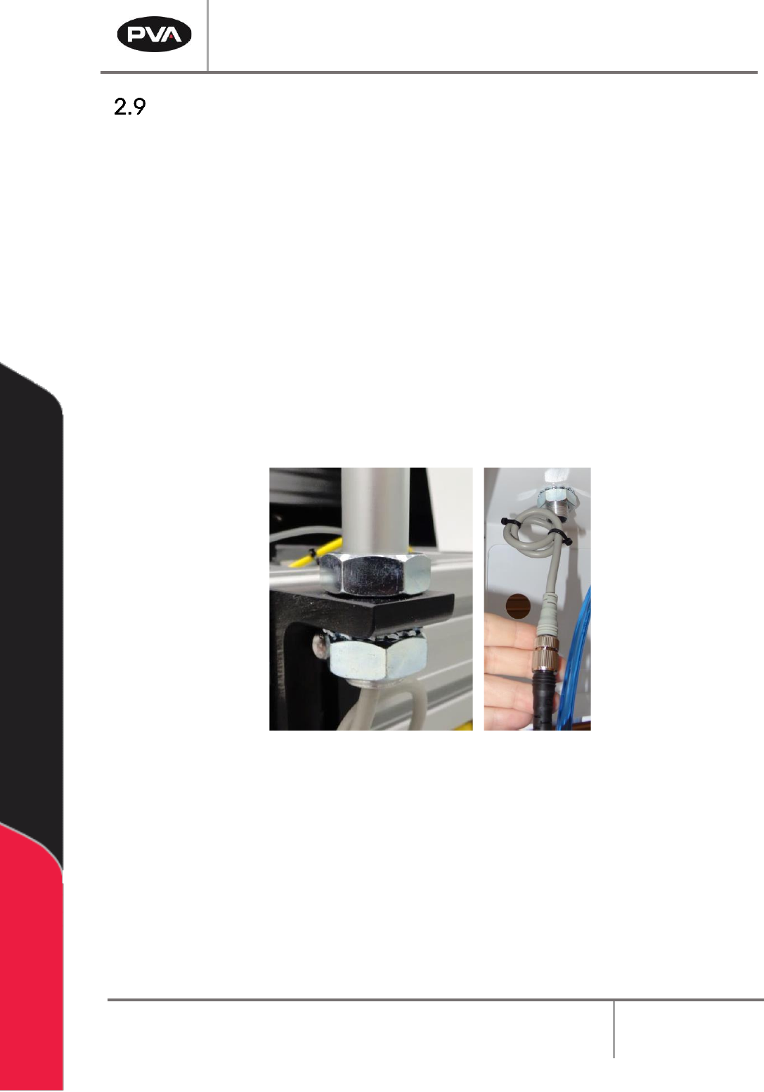
Install Light Tower
1. Find the light tower on the top rear of the workcell.
2. Remove all packaging and material from the light tower, this includes: wrapping
paper, bubble pack, and tape.
3. Find the light tower connection on the top of the workcell.
4. There will be a nut on the top of the workcell and a lock nut and washer inside the
workcell. Remove the bottom lock nut and washer.
5. Align the mast to the extrusion. The power cord should go through the hole down
inside the workcell.
6. Tighten the lock nut to the bottom of the light tower mast. Use an adjustable
wrench as necessary to tighten.
7. Connect the two ends of the light tower cables.
Figure 9: Light Tower Connection

Workcell Installation and General Guidelines
Revision F / January 2021
Page 20 of 59
Level the Workcell
This is the procedure to level the workcell. If the workcell will be used as an in-line system,
it needs to be leveled and aligned with the upstream and downstream systems. This
document does not include procedures for upstream and downstream systems. Alignment
procedures should be developed and followed by your facility.
1. Put the level in the center of the front conveyor.
2. Look at the position of the bubble in the level window. The bubble will be centered
between the two lines when the workcell is level.
TIP: If the bubble is outside or closer to the right line, raise the left side of the
workcell. If the bubble is outside or closer to the left line, raise the right side of the
workcell.
3. If necessary, loosen the locking nut on each foot with an adjustable wrench.
4. Use an adjustable wrench to adjust the feet of the workcell. Put the wrench on the
flat (unthreaded) part of the pedestal and turn in the necessary direction until the
workcell is level from side to side.
TIP: Turn the pedestal clockwise to raise the workcell and counterclockwise to lower
the workcell. See Figure 2.
5. Put the level along the length of the rail to check for level at both ends of the
conveyor’s rails.
6. Look at the position of the bubble in the level window. The bubble will be centered
between the two lines when the workcell is level. Do steps 3 and 4 to make the
workcell level.
7. Put the level across the center of the conveyor’s rails, with one end on the front
conveyors and one end on the back rail.
8. Look at the position of the bubble in the level window. The bubble will be centered
between the two lines when the workcell is level. Complete steps 3 and 4 to make
the workcell level.
9. In each corner, put your hands on top of the workcell and push down. If one of the
feet does not touch the ground the workcell will rock back and forth. Adjust the feet
so that they all bear equal weight.
10. After you check the corners, level the workcell from side to side and front to back
again, if necessary.
11. When the workcell is level from front to back and side to side, is stable, and all four
feet bear equal weight, use your hand to turn the locking nuts on the workcell feet
counterclockwise until they are tight.
Workcell Installation and General Guidelines
Revision F / January 2021
Page 21 of 59
Power Up
After the accessories are installed, connect the workcell to air and power supplies. After
the workcell is correctly connected, turn the main power switch “On” and make sure
system components function correctly.
WARNING: Failure to obey electrical specifications can damage the machine and
injure personnel. Electrical hookup must be done by a qualified electrician and must
comply with any applicable local standards.
1. Plug the machine into an appropriate power source as shown on the legend plate on
the rear of the machine.
The electrical service must be correctly grounded and the power source “clean”. If high-
power equipment uses the same source, a line conditioner may be necessary. Poor power
quality can cause machine errors. All workcells shipped from the PVA factory can operate
with the voltage used at the installation site, per engineering design.
WARNING: Make sure that the main power switch is “Off” before you connect the
workcell to the facility power source.
2. Find the main air regulator.
3. Attach the workcell to the facility air supply. There is a ¼” NPT female fitting at the
rear of the machine. Connect to a source of clean, dry air. Compressed air with a
dew point of 50° F (10° C) is sufficient. A hose with ¼” inside diameter is sufficient
for most machines and typical air consumption is 2-6 CFM (3.4 to 10.2 m^3/hr).
4. Slowly open the facility air valve.
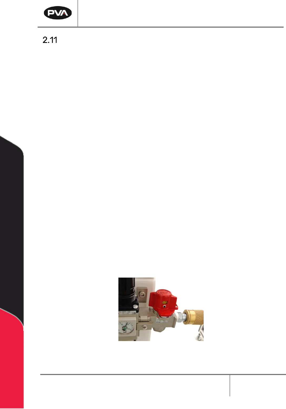
5. Close any access doors and engage in the Emergency Stop button.
6. At the rear of the machine, turn on the red air lockout valve.
Figure 10: Example of a Red Air Lockout Valve