Workcell-Installation-Guidelines-Troubleshooting-Maintenance-REV-F.pdf - 第16页
Workcell Installation and General Guidelines Revision F / Janu ary 2021 Page 16 of 59 Servo Motor Couplings Servo couplings are compensating couplings t hat are backlas h free with c onformal tor que transfer. They su pp…
Workcell Installation and General Guidelines
Revision F / January 2021
Page 15 of 59
Board Sensor Sensitivity Adjustment Procedures
Board sensors are optic sensors that face upward along the length of the front of the
conveyors. They detect the presence of a part and send a signal to the motion controller. If
a board is reflective or shiny, or does not process correctly adjust the board sensors.
The number of sensors depends on your system, but your workcell may have up to five
board sensors. There can be one for each zone (entry zone, primary spray/work area, exit
zone, return work area, and part detection). Adjust each sensor as necessary.
To Adjust the Board Sensors
You will need a small flat head screwdriver and part or sample board to be processed.
1. Put a part on the conveyor’s rail and examine sensor sensitivity.
2. To increase sensitivity, use a small screwdriver to turn the sensor screw clockwise.
To decrease sensitivity turn the sensor screw counterclockwise.
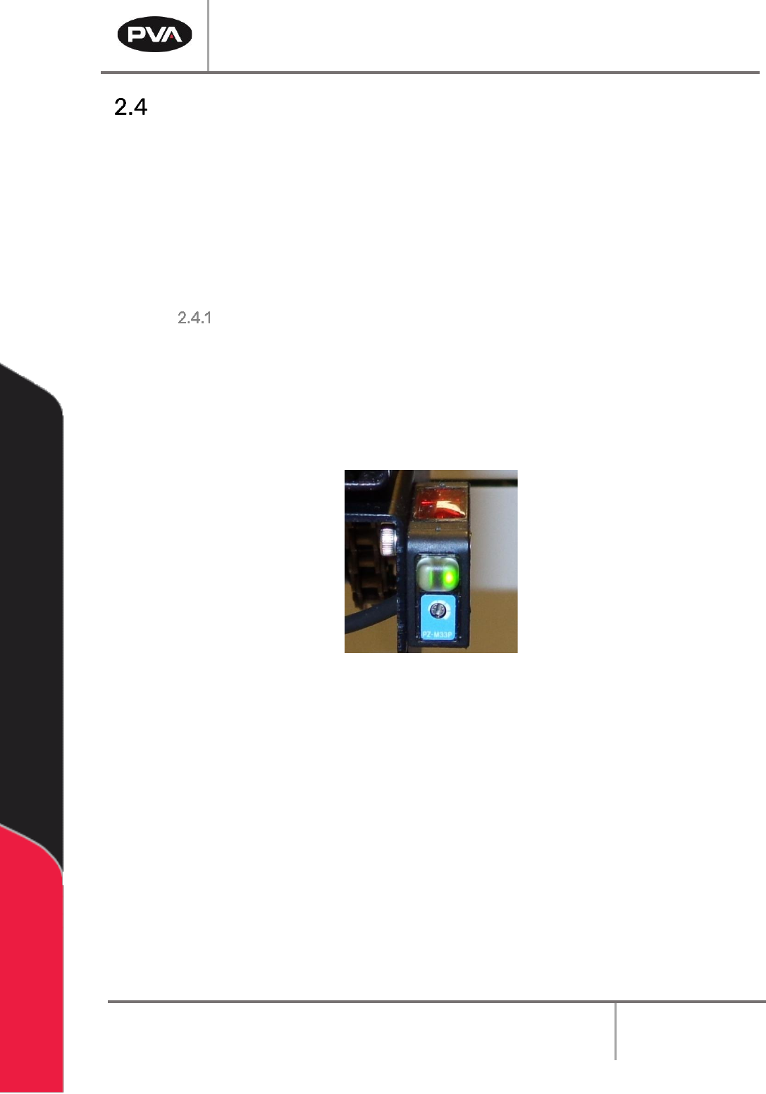
Figure 5: Board Sensor
3. Use the sample part to examine the board sensors on both sides (top and bottom) of
the conveyors.
4. If only the green LED is on, the sensor is OFF. If the Orange LED is on the sensor is ON.
Workcell Installation and General Guidelines
Revision F / January 2021
Page 16 of 59
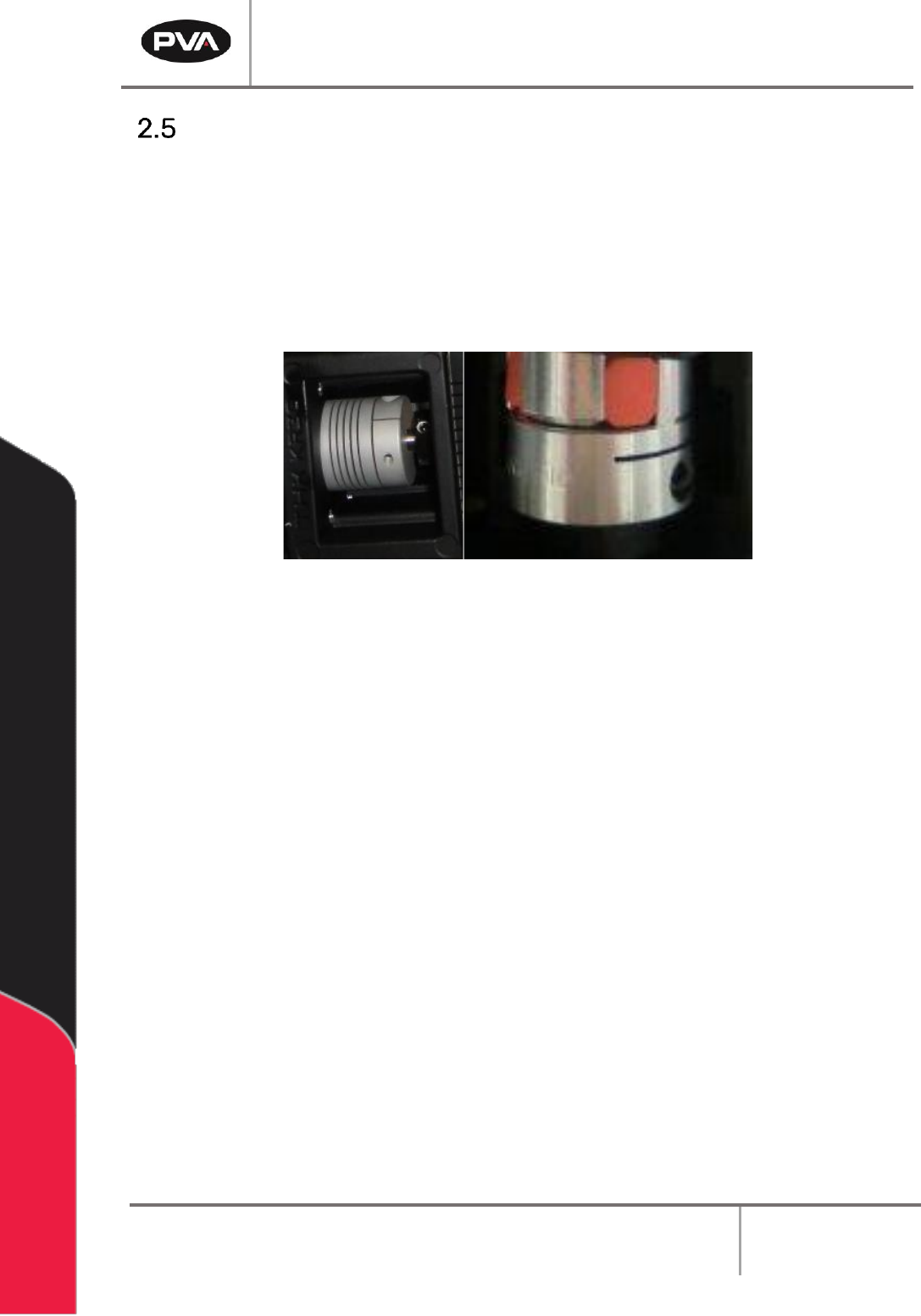
Servo Motor Couplings
Servo couplings are compensating couplings that are backlash free with conformal torque
transfer. They supply high torsion stiffness and a low moment of inertia. Examine the servo
motor couplings if shifting is suspected and to tighten the set screws.
Note: It may be necessary to remove the motor to get access to the second set
screw. The second set screw is not always visible but must also be tightened
periodically.
Figure 6: Servo Couplings
Workcell Installation and General Guidelines
Revision F / January 2021
Page 17 of 59
Inspection
1. Open the doors and remove all straps, tie wraps, and sponges around the dispense
heads and gantry.
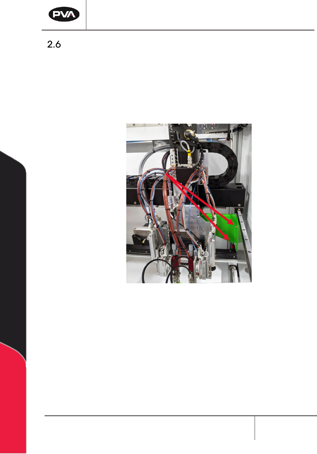
NOTE: In order to prevent any movement during the shipping process, many
workcells are equipped with green shipping brackets inside the machine. The
placement of these brackets will vary by workcell. The shipping brackets must be
removed before continuing the inspection.
Figure 7: Shipping Bracket
2. Fully examine the workcell for damage, loose fasteners, etc.
3. Use your hands to move the X and Y-axis slide to the center of the work area.
4. Examine all tubing connections, gauges, and regulators.
5. Open the electrical enclosure and visually inspect connectors and components for
signs of vibration during shipping. Close the door, the machine should not operate
with the doors open.
6. Make sure all cables and connections are fully and correctly installed.