Workcell-Installation-Guidelines-Troubleshooting-Maintenance-REV-F.pdf - 第23页
Workcell Installation and General Guidelines Revision F / Janu ary 2021 Page 23 of 59 M achine Communicati ons (SMEMA) For manufacturi ng lines (multiple m achines with co nveyor syst ems) SMEMA cabl e s must be connecte…
Workcell Installation and General Guidelines
Revision F / January 2021
Page 22 of 59
7. Ground any pressure vessel to earth or the machine.
8. Attach a correctly designed ventilation system to the exhaust port. It is necessary
that the exhaust flow is correct for the specified CFM of your workcell.
NOTE: Refer the Material Safety Data Sheets (MSDS) for safety precautions on any
chemicals used in PVA equipment.
NOTE: Do not power on the workcell or add material to the pressure vessels until
they are correctly grounded.
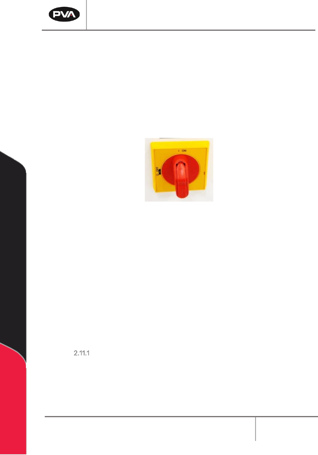
9. Turn the main power switch “On”.
Figure 11: Example of a Main Power Switch
10. Do the safety check and homing routine through Portal.
11. Select Manual mode and manually (using teach pendant) move the head around the
entire work area. Make sure there are no components that can be hit by the head in
the work area.
12. Make sure that the pneumatic and electrical cables do not decrease the heads travel
and will not be cut or snagged when moved. Please contact Technical support if
there are any problems.
13. Make sure the valve and brackets are tight and that the valve does not rock or
wiggle in the bracket.
14. Close the doors.
LCD Mounting Requirements
If a monitor will be mounted on a PVA arm it must:
• Weigh no more than 9 lbs.
• Have either 75mm or 100mm hole spacing for the VESA mount.
• Be flat on rear of the monitor for PVA keyboard tray bracket.
Workcell Installation and General Guidelines
Revision F / January 2021
Page 23 of 59
Machine Communications (SMEMA)
For manufacturing lines (multiple machines with conveyor systems) SMEMA cables must
be connected in the correct manner for the individual modules to communicate reliably.
Not all workcells have SMEMA plugs. Please note on the diagrams the J# refers to the label
on the machine, not the label on the cable.
The Surface Mount Equipment Manufacturers Association (SMEMA) Electrical Equipment
Interface Standard is used to make sure the sequence of boards is correct. If you do not
have these connections, boards cannot move from one machine to another. SMEMA cables
have male 14-pin, amp-type CPC connectors. The cables are straight through, so
orientation does not matter. SMEMA machine plugs may be on the inside or the outside of
the machine, depending on the workcell.
Each machine must have the same transport conveyor height from the floor to the bottom
of the PC board. For equipment with an adjustable conveyor width, the front rail is not
adjustable. The range of adjustment will change with the workcell.
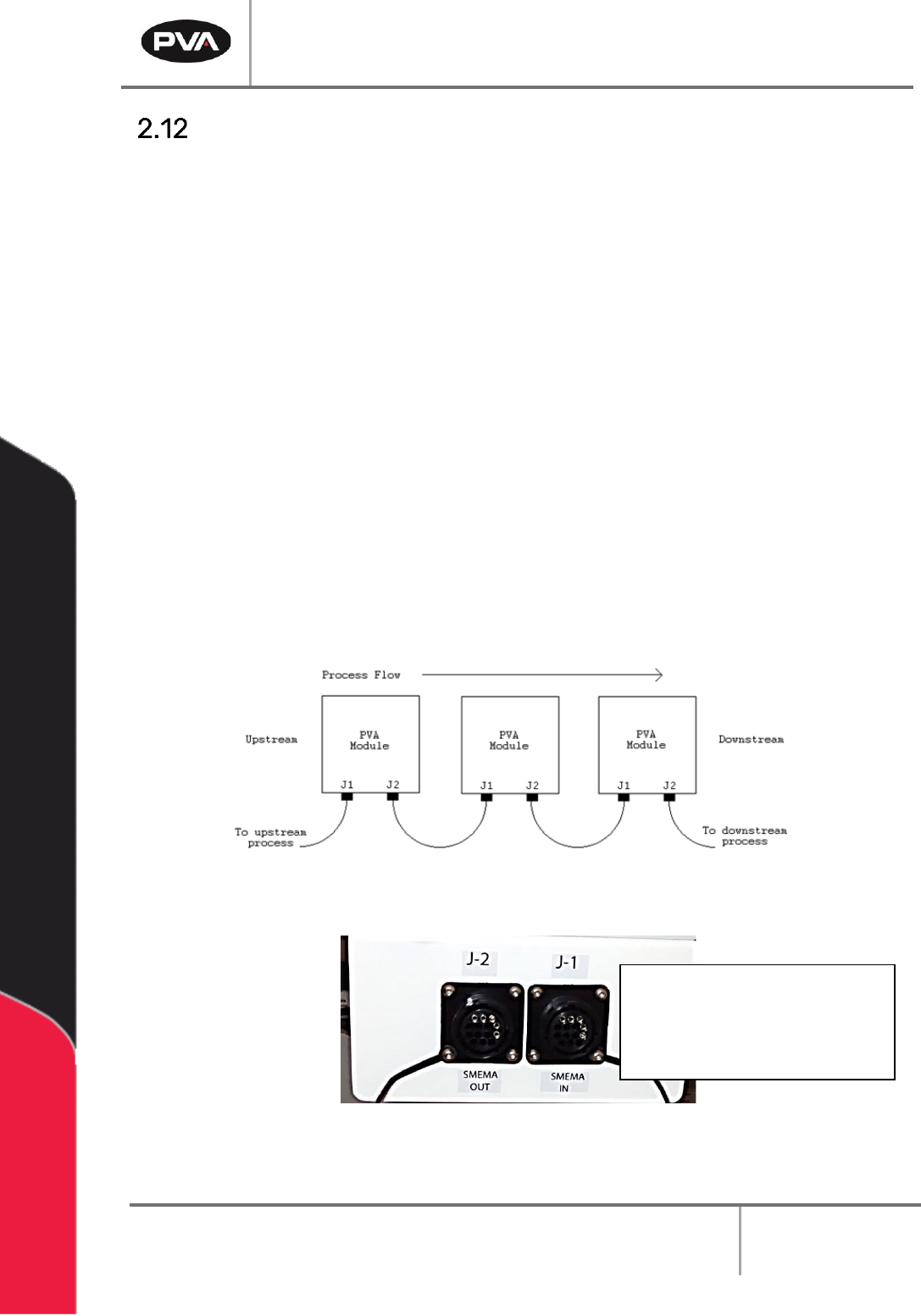
Two signal lines will be used: Ready and Board Available. On each module, the cable to the
J1 (Previous) plug must connect to the J2 (Next) plug on the machine upstream. The J2
plug on each machine must connect to the J1 plug on the machine downstream, as shown
in the following diagram:
Figure 12: SMEMA Diagram
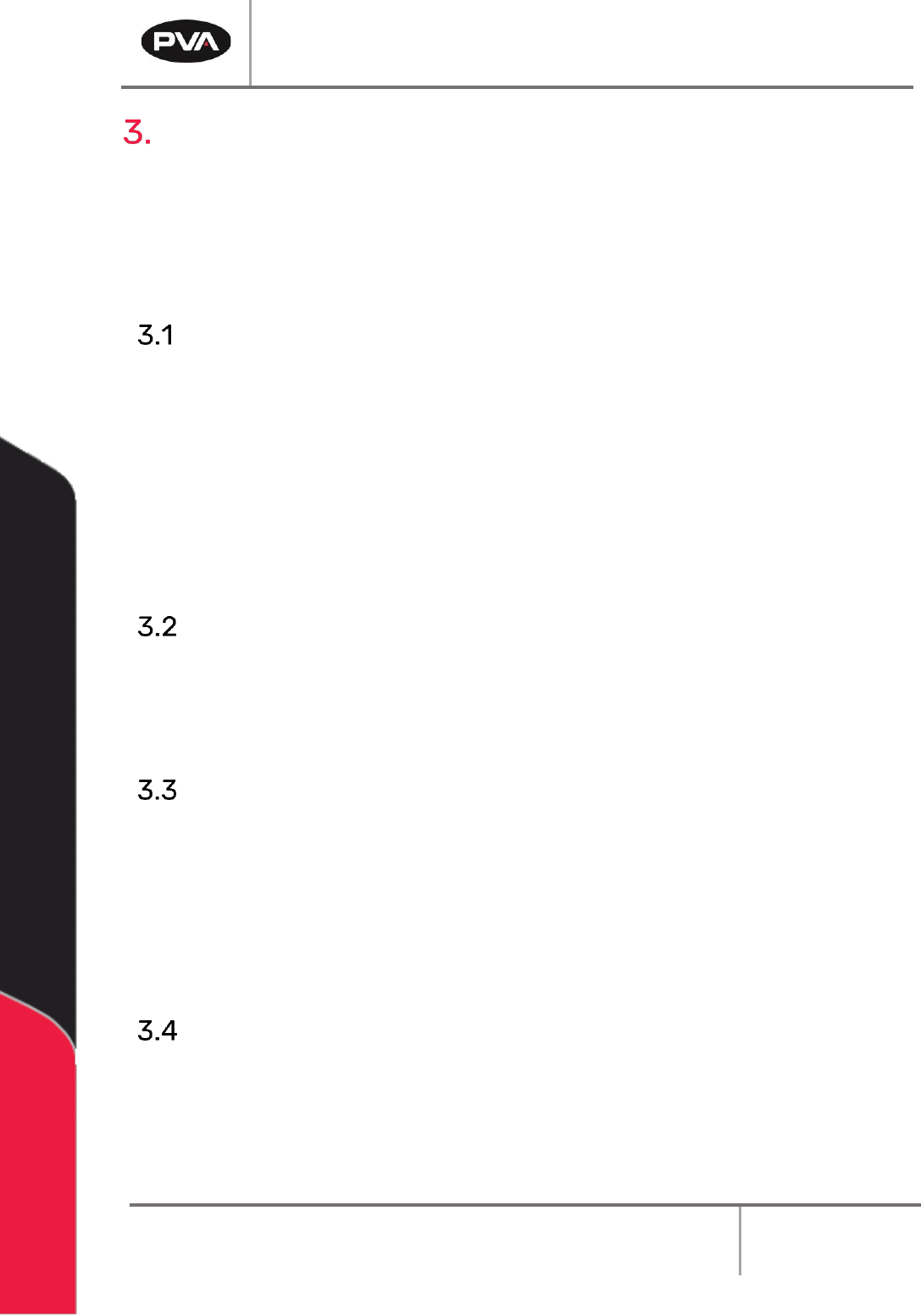
Figure 13: SMEMA Machine Plugs
NOTE: For bidirectional
machines there may be J3
and J4 that follow J1 and
J2 respectively.
Workcell Installation and General Guidelines
Revision F / January 2021
Page 24 of 59
Operating Safety
The workcell has several safety features that protect the operator from hazards in normal
machine operation.
Warning! The safety features should NEVER be bypassed, disabled, or tampered with.
PVA is not responsible for any damage, mechanical or human, caused by changes or
destruction of any safety features.
Safety Circuit
The main power to the workcell is monitored and controlled by the safety circuit. The
safety circuit contains two relays under-voltage protection and one or more safety
devices. The relays are wired in a redundant manner. The tripping contacts of the relays
are connected in series so the safety circuit will disconnect power even if one of the relays
fails. The relays are self-checking with positive guided contacts electrically forced to
operate together. If one redundant relays fails or a safety switch is activated, the power
contacts are opened.
Polycarbonate and Safety Glass Guarding
The work area is enclosed with either polycarbonate or safety glass guarding. The front of
the workcell is either open, for the manual processing of parts, or has doors.
Doors
Workcells with an automatic load/unload cycle will have one or two doors in the front. Each
door is monitored by a non-defeatable limit switch. When a door is opened, power to the
motors and pneumatics is disconnected. The DOOR BYPASS key switch is for maintenance
personnel to access the work area without disconnecting power. The bypass switch can
only be used in manual or calibration mode.
Light Curtain
Some workcells have a light curtain. The light curtain is redundant and self-checking. The
control signals from the light curtain are safety devices in the safety circuit.