Workcell-Installation-Guidelines-Troubleshooting-Maintenance-REV-F.pdf - 第44页
Workcell Installation and General Guidelines Revision F / Janu ary 2021 Page 44 of 59 Common Main Program Changes Variable Explanation AP_EN Default valu e for auto p urge. 1=on, 0=off. AP_LEN Length of auto purg e, in m…
Workcell Installation and General Guidelines
Revision F / January 2021
Page 43 of 59
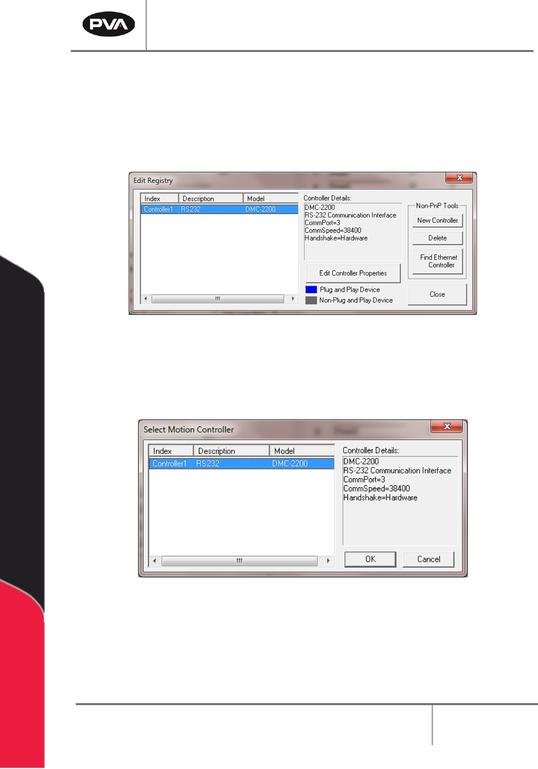
14. To make changes, highlight the controller and select “Edit Controller Properties”.
15. Multiple control handles can be added.
16. To delete control handles, select the control handle and select “Delete”.
17. Select “Close” when you are finished.
Figure 29: Edit Registry
18. Select the “Change Controller” button in the Machine Parameters window to
change the controller that PathMaster® uses with the workcell.
19. Select the controller to be used.
Figure 30: Change Controller
20. Select the “OK” button.
Workcell Installation and General Guidelines
Revision F / January 2021
Page 44 of 59
Common Main Program Changes
Variable
Explanation
AP_EN
Default value for auto purge. 1=on, 0=off.
AP_LEN
Length of auto purge, in milliseconds.
AP_TIME
Time between auto purges, in milliseconds.
SLP_TM
Sleep timer value for solvent rest, in milliseconds.
SO_EN
Solvent rest enable/disable. 1=enable, 0=disable.
Figure 31: Variable Explanations
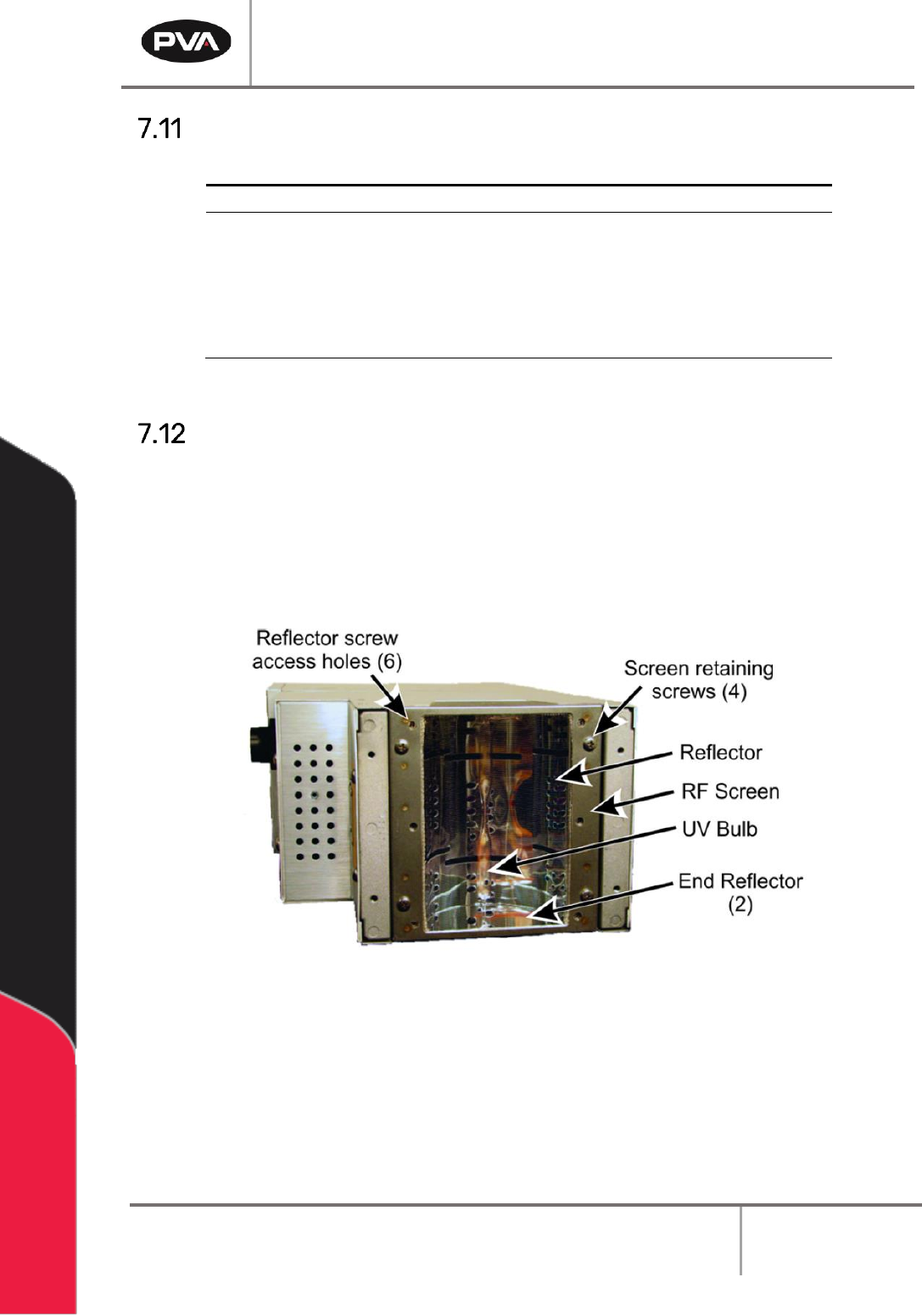
Install Spectra Lamp
1. Unpack the Spectra from crating.
2. Locate the irradiator (lamp) package(s) and carefully remove the lamps from the
packaging.
3. Place the irradiator on a flat surface so that the bulb/screen side is accessible.
Figure 32: Irradiator Bulb Side
4. Make sure that the reflectors, bulb, and RF screen are installed properly. Refer to
Heraeus F300S manual for more details.
Workcell Installation and General Guidelines
Revision F / January 2021
Page 45 of 59
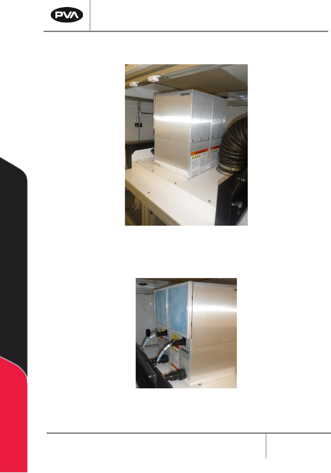
5. Install irradiators into the Spectra carefully by placing the light/screen side facing
down.
Figure 33: Install Irradiators
6. If there is more than one lamp, place all lamps in place before the next step.
7. Connect the lamp cables, taking note of the labels on the cables and lamps.
Figure 34: Connect Lamp Cables