Workcell-Installation-Guidelines-Troubleshooting-Maintenance-REV-F.pdf - 第59页
Workcell Installation and General Guidelines Revision F / Janu ary 2021 Page 59 of 59 Figure 41: Submit a Tick et ................................................................ .........................................…
Workcell Installation and General Guidelines
Revision F / January 2021
Page 57 of 59
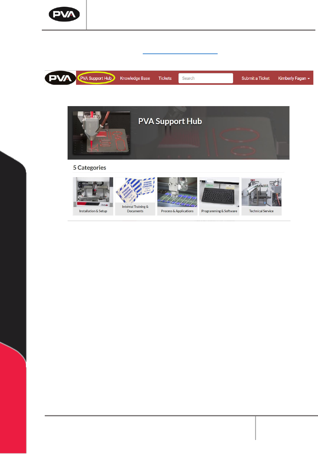
8. You can also acess the PVA Support Hub from “PVA Support Hub” option in the
header or through the link https://support.pva.net/. The support hub has processes
and procedures on common topics and issues.
Figure 44: PVA Support Hub
Figure 45: Support Hub Website

Workcell Installation and General Guidelines
Revision F / January 2021
Page 58 of 59
Table of Figures
Figure 1: Workcell Functional Block Diagram ...................................................................................... 9
Figure 2: Light Tower & Buzzer Status .............................................................................................. 12
Figure 3: Adjust the Feet ....................................................................................................................... 14
Figure 4: Light Tower & Buzzer Status .............................................................................................. 14
Figure 5: Board Sensor .......................................................................................................................... 15
Figure 6: Servo Couplings ..................................................................................................................... 16
Figure 7: Shipping Bracket .................................................................................................................... 17
Figure 8: Teach Pendant Connection ................................................................................................. 18
Figure 9: Light Tower Connection ....................................................................................................... 19
Figure 10: Example of a Red Air Lockout Valve ................................................................................ 21
Figure 11: Example of a Main Power Switch ..................................................................................... 22
Figure 12: SMEMA Diagram .................................................................................................................. 23
Figure 13: SMEMA Machine Plugs ....................................................................................................... 23
Figure 14: Measure Velocity at Port ................................................................................................... 26
Figure 15: Measure Velocity at Duct Inlet ......................................................................................... 26
Figure 16: Portal Shell ............................................................................................................................ 27
Figure 17: Workcell Manual Location ................................................................................................... 27
Figure 18: Systems Fault Diagnosis ................................................................................................... 30
Figure 19: Preventive Maintenance Schedule ................................................................................. 32
Figure 20: Terminal Window ................................................................................................................ 36
Figure 21: Terminal Screen Commands ............................................................................................. 37
Figure 22: Encoder Feedback Test .................................................................................................... 39
Figure 23 .................................................................................................................................................. 40
Figure 24: Setup New Controller ........................................................................................................ 40
Figure 25: Controller Models ................................................................................................................ 41
Figure 26: Connection Type ................................................................................................................. 41
Figure 27: Serial Parameters ............................................................................................................... 42
Figure 28: Controller Added ................................................................................................................ 42
Figure 29: Edit Registry ........................................................................................................................ 43
Figure 30: Change Controller .............................................................................................................. 43
Figure 31: Variable Explanations......................................................................................................... 44
Figure 32: Irradiator Bulb Side ............................................................................................................ 44
Figure 33: Install Irradiators ................................................................................................................ 45
Figure 34: Connect Lamp Cables ....................................................................................................... 45
Figure 35: Turn Lamp Power Supply On ........................................................................................... 46
Figure 36: Important Commands ....................................................................................................... 52
Figure 37: DMC Error Codes ................................................................................................................. 53
Figure 38: Support Portal ..................................................................................................................... 54
Figure 39: Log In .................................................................................................................................... 54
Figure 40: Sign In or Register .............................................................................................................. 55

Workcell Installation and General Guidelines
Revision F / January 2021
Page 59 of 59
Figure 41: Submit a Ticket .................................................................................................................... 55
Figure 42: Complete the Ticket .......................................................................................................... 56
Figure 43: Example Ticket Email......................................................................................................... 56
Figure 44: PVA Support Hub ................................................................................................................ 57
Figure 45: Support Hub Website .......................................................................................................... 57