Workcell-Installation-Guidelines-Troubleshooting-Maintenance-REV-F.pdf - 第37页
Workcell Installation and General Guidelines Revision F / Janu ary 2021 Page 37 of 59 The motors m ay be wired incorrectly. Th e program below limits the acceptabl e error and power available to the ampl ifiers. This pro…
Workcell Installation and General Guidelines
Revision F / January 2021
Page 36 of 59
Motor Feedback Test
Use this procedure to make sure that the motor power and Hall Effect sensors are wired
correctly. If a problem is found with any of the axes, repair it and tell a production supervisor.
WARNING! Make sure that the workspace has no parts or objects in it. If the axis runs
away, the machine can be irreversibly damaged.
1. Turn the machine “ON”.
2. Engage the “Emergency Stop” button. This stops the power to the amplifiers.
3. Open a terminal program and establish communication with the motion controller,
this can be done with the ‘terminal’ option in PathMaster® or PVA Portal.
4. Enter HX and MO in the terminal screen
5. Disengage the “Emergency Stop” push button.
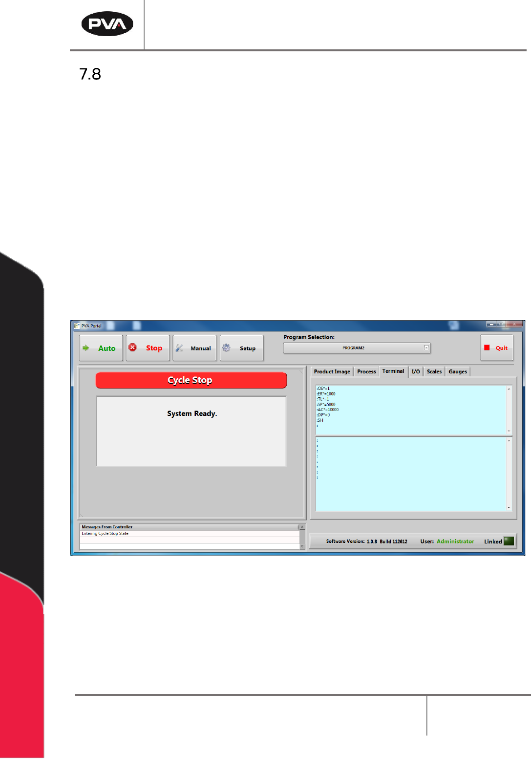
Figure 20: Terminal Window

Workcell Installation and General Guidelines
Revision F / January 2021
Page 37 of 59
The motors may be wired incorrectly. The program below limits the acceptable error and
power available to the amplifiers. This protects personnel and equipment.
6. Enter the commands that follow on the terminal screen.
OE*=1
Off-on-error enabled for all axes
ER*=1000
Error limit for all axes
TL*=1
Torque limit of 1 for all axes
SP*=5000
Set the speed
AC*=10000
Set the acceleration
DP*=0
Define the current position as (0, 0, 0, 0)
SBN
Enable power (only on machines without a POWER ON button) where N = the
control output power bit, refer to electrical schematic or call PVA Technical
Support
SH
Apply power to the servo motors
Figure 21: Terminal Screen Commands
7. Push the “POWER ON” button (if present) so it lights up. This restores power to the
amplifiers. Use caution, any of the axes can move at this time.
8. Enter an X-axis positive move command. If the axis runs away, debug and do the
procedure again.
PRX=2000
BGX
If the results are not correct, make sure the command was entered correctly and repeat the
previous tests.
9. Enter the command to see the current position and position error, TP; TE.
10. Enter an X-axis negative move command. If the axis runs away debug and do the
procedure again.
PRX=-2000
BGX
11. Enter the command to see the current position and position error, TP; TE.
12. Repeat step 6 through 10 for the Y, Z and W axes. Replace the X in both commands
with the necessary axis. Example for the Y axis it would be:
PRY=2000
BGY

Workcell Installation and General Guidelines
Revision F / January 2021
Page 38 of 59
Encoder Feedback Test
Use this procedure to test the encoder feedback for all of the axes. If a problem is found with
any of the encoders, repair it and then report the error to a production supervisor. Most
encoders used with Portal generate 5080 counts/inch. Make sure that the position feedback
is in the correct range.
(500*4 counts/rev)*(1 rev/cm)*(2.54 cm/in) = 5080 counts/inch.
1. Turn the machine “OFF” and disconnect the motor power.
2. Move all of the axes to the center of travel position.
3. Turn the machine “ON”.
4. Login to PVA Portal.
5. Select the terminal tab. Push “Enter”. You should see a colon response.
6. Enter HX.
7. Define the current position as (0, 0, 0, 0). Enter DP*=0.
8. Use your hand to move the X-axis in the positive direction and look at the current
position. The current position should reflect the numbers listed above (5080
counts/inch, 2000 counts/rev, or 200 counts/mm).
9. Enter TP.
10. Refer to step 10 for steps 13-19.
11. Move the X-axis in the negative direction and look at the current position.
12. Move the Y-axis in the positive direction and look at the current position. Move the Y-
axis in the negative direction and look at the current position.
13. Move the Z-axis in the positive direction and look at the current position. Move the Z-
axis in the negative direction and look at the current position.
14. Move the W-axis in the positive direction and look at the current position. Move the
W-axis in the negative direction and look at the current position.
15. Select “Quit” to shutdown Portal.
16. Shutdown the PC.