slau358q.pdf - 第10页
5 in (127 mm) 5.7 in (145 mm) 2 in (51 mm) 3.5 in (89 mm) SD Card RS232 USB Height = 0.67 in (17 mm) Height = 0.95 in (24 mm) Software Installation www.ti.com 10 SLAU358Q – September 2011 – Revised October 2019 Submit Do…

9
SLAU358Q–September 2011–Revised October 2019
Submit Documentation Feedback
Copyright © 2011–2019, Texas Instruments Incorporated
Introduction
Chapter 1
SLAU358Q– September 2011 –Revised October 2019
Introduction
The MSP Gang Programmer for the MSP430 and MSP432 microcontrollers can program up to eight of the
same MSP flash or FRAM devices at one time. The MSP Gang Programmer connects to a host PC using
a standard RS-232 or USB connection and provides flexible programming options that allow the user to
fully customize the process. Figure 1-1 shows a top-level view of the MSP Gang Programmer.
The MSP Gang Programmer is not a gang programmer in the traditional sense, in that there are not eight
sockets to program target devices. Instead, the MSP Gang Programmer connects to target devices that
are mounted in the final circuit or system. The MSP Gang Programmer accesses the target devices
through connectors that use JTAG, Serial-Wire Debug (SWD), Spy-Bi-Wire (SBW), or bootloader (BSL)
signals.
The MSP Gang Programmer includes an expansion board, called the Gang Splitter, that connects the
MSP Gang Programmer to multiple target devices. Eight cables connect the Gang Splitter to eight target
devices (through JTAG, SWD, SBW, or BSL connectors). For MSP432 MCUs, an adapter kit (MSP-
GANG-432ADPTR) can convert from 14-pin JTAG connectors to 20-pin Arm connectors.
Chapter 2 describes how to use the MSP Gang Programmer to program target devices. This chapter
describes the modes of operation and how to choose the method of programming. This chapter also
describes the user interface that defines how to program the target device.
Chapter 3 describes firmware commands that give low-level control of the programming process. The
commands correspond to specific actions that the programmer can perform. The MSP Gang Programmer
connects to a host computer through a RS-232 or USB port to receive the commands. Often, you must
use the commands in groups or in a specific order to ensure proper behavior.
Chapter 4 describes Gang430.dll, MSP-GANG.dll, and the functions that are available through them.
Chapter 5 contains an I/O schematic that shows how signals from the MSP Gang Programmer go to each
target device through an MSP-standard JTAG, SWD, SBW, or BSL connector. To make a traditional gang
programmer, you can change the circuit to connect the signals to the target device pins directly through a
socket.
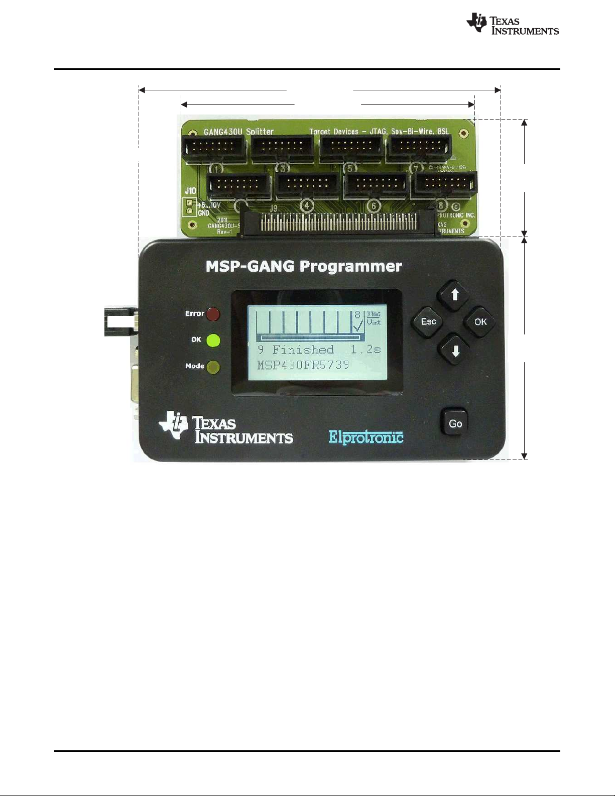
5 in (127 mm)
5.7 in (145 mm)
2 in
(51 mm)
3.5 in
(89 mm)
SD Card
RS232
USB
Height = 0.67 in (17 mm)
Height =
0.95 in (24 mm)
Software Installation
www.ti.com
10
SLAU358Q–September 2011–Revised October 2019
Submit Documentation Feedback
Copyright © 2011–2019, Texas Instruments Incorporated
Introduction
NOTE: Dimensions are approximate.
Figure 1-1. Top View of the MSP Gang Programmer
1.1 Software Installation
Use the latest software version, which can be downloaded from the MSP-GANG Production Programmer
tool folder. The MSP-GANG Programmer Software runs on Windows
®
32 bit or 64 bit: Windows XP,
Windows 7, Windows 8, and Windows 10.
To install MSP Gang Programmer software:
1. Unzip the installation package.
2. Run setup.exe in the root directory of the package.
3. Follow the instructions in the installation process.
4. When the setup program finishes, click the MSP Gang Programmer Read Me First icon to read
important information about the MSP Gang Programmer.
5. The setup program also adds a program group and icons to the Windows desktop.
6. To start the MSP Gang Programmer software, click the icon.

www.ti.com
Driver Installation
11
SLAU358Q–September 2011–Revised October 2019
Submit Documentation Feedback
Copyright © 2011–2019, Texas Instruments Incorporated
Introduction
1.2 Driver Installation
To install the required drivers:
1. Connect the MSP-GANG programmer to a PC USB port. When the Windows wizard starts, follow the
instructions provided by wizard. When the wizard asks for the USB driver location, browse to the CD-
ROM drive. Drivers are in the main CD-ROM directory location and also in the following directory:
C:\Program Files\Texas Instruments\MSP-GANG\Driver
2. If the RS-232 interface is used for communication with MSP-GANG, the USB driver is not required.
Run the Windows Device Manager to find for the COM port number to use with communication through
RS-232.
1.3 Hardware Installation
To install the MSP Gang Programmer hardware:
1. Attach the expansion board (Gang Splitter) to the 100-pin connector on the MSP Gang Programmer.
The expansion board connects up to eight targets using the included 14-pin cables. The target
MSP430 flash devices can be in stand-alone sockets or can be on an application PCB. The MSP Gang
Programmer can connect to these devices through JTAG, SBW, or BSL signals.
If the target device is an MSP432 MCU, use the adapter kit (MSP-GANG-432ADPTR) to convert from
14-pin JTAG connectors to 20-pin Arm connectors.
2. Connect the MSP Gang Programmer hardware to the computer USB port using a USB A-B cable.
The USB port (5 V, 0.5 A) can supply the programmer.
If the computer does not have a USB port, connect the programmer to a serial port (COM1 to
COM255) using a 9-pin Sub-D connector.
3. If the MSP Gang Programmer is not connected through the USB port, or if the total current
consumption of the programmed target devices exceeds 0.3 A, connect an external power supply to
the programmer.
NOTE: External Power Supply
An external power supply must provide a voltage between 6 V and 10 V DC and must
provide a minimum current of 800 mA. The center post of the power supply connector on the
MSP Gang Programmer is the positive-voltage terminal. The programmer indicates the
status of the power supply connection by using system LEDs and the LCD back light.
NOTE: Maximum Signal Path Length: 50 cm
The maximum length of a signal path between the 14-pin JTAG or SBW connector on the
Gang Splitter and the target device is 50 cm.
4. The MSP Gang Programmer can supply power at a specified voltage V
CC
to each target device (pin 2
on each 14-pin JTAG, SBW, SWD, or BSL cable). The maximum current for each target device is
programmable to 30 mA or 50 mA. If the higher current limit is selected (50 mA) and eight target
devices are connected, then the total current to all devices can reach up to 400 mA. In this case, the
connect an external power supply to the MSP Gang Programmer. The USB cannot supply this current,
because the USB port maximum current is 0.5 A, and the MSP Gang Programmer uses 150 mA,
leaving 350 mA for the target devices.