slau358q.pdf - 第22页
Programming MSP Flash Devices Using the MSP Gang Programmer www.ti.com 22 SLAU358Q – September 2011 – Revised October 2019 Submit Documentation Feedback Copyright © 2011–2019, Texas Instruments Incorporated Operation Fig…
www.ti.com
Programming MSP Flash Devices Using the MSP Gang Programmer
21
SLAU358Q–September 2011–Revised October 2019
Submit Documentation Feedback
Copyright © 2011–2019, Texas Instruments Incorporated
Operation
NOTE: MSP Gang Programmer internal memory and SD-Card are mutually exclusive.
To avoid confusion during programming, connecting an SD-Card to the MSP Gang
Programmer disables its internal memory used for other images. Therefore, when an SD-
Card is connected to the programmer only the image on the SD-Card is usable or
accessible. If the SD-Card is empty, or contains a corrupted image, then it must be
disconnected before MSP Gang Programmer internal memory can be used.
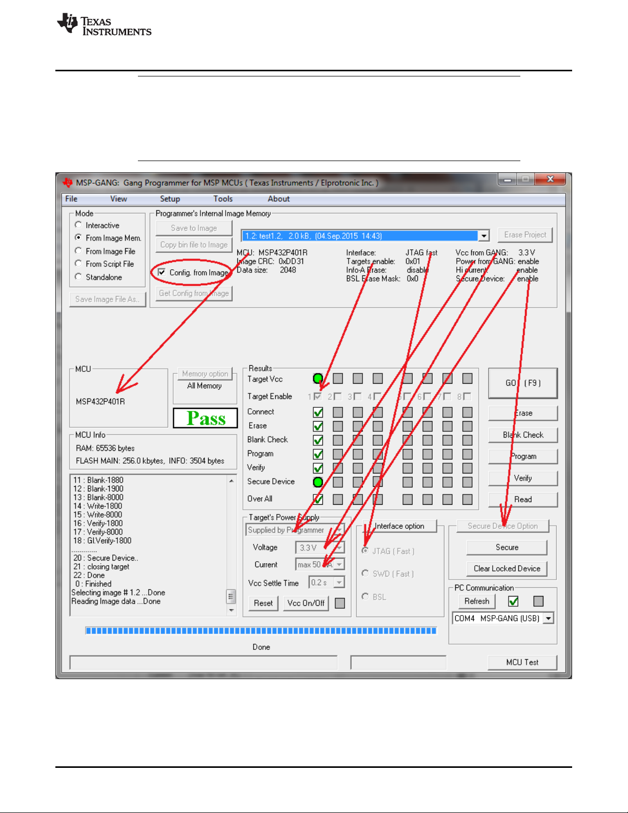
NOTE: This figure shows the From Image Mode (see the Mode section near the top left corner). The user can
load an image from MSP Gang Programmer internal memory. Saved images contain all configuration
necessary for programming and all code files. An image can be created using the Interactive Mode and
saved to the programmer. One of 96 different images can be selected from internal memory, or one image
from each external SD-Card can be used.
Figure 2-6. Main MSP Gang Programmer Dialog GUI, From Image Mode

Programming MSP Flash Devices Using the MSP Gang Programmer
www.ti.com
22
SLAU358Q–September 2011–Revised October 2019
Submit Documentation Feedback
Copyright © 2011–2019, Texas Instruments Incorporated
Operation
Figure 2-6 highlights several parts of the GUI. The drop-down menu in the Object in Image memory group
(top right) is used to select which image is used for programming, because up to 96 different images might
be available. In the same group, the Config. from Image option is enabled, meaning that all configurations
options, such as which devices are enabled or power options are being taken from the image.
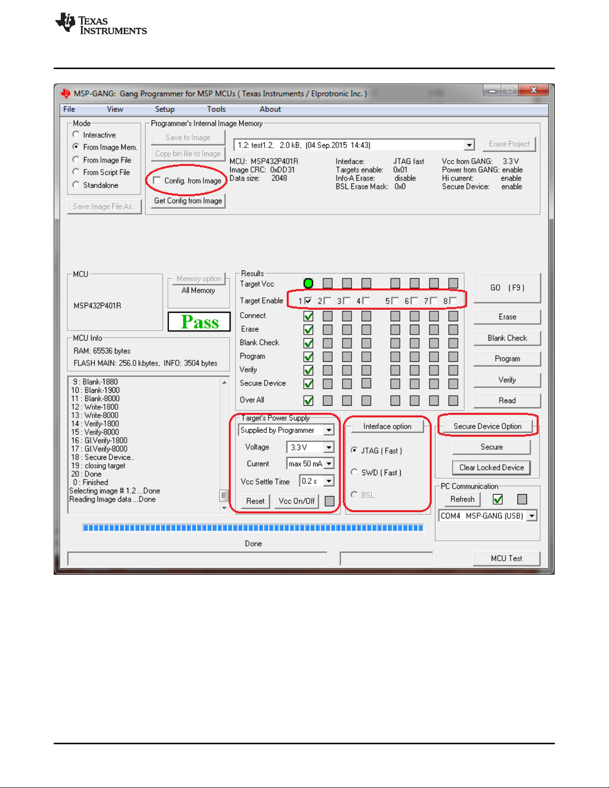
Sometimes it is useful to use the basic files from an image, such as the MCU type and code files, but also
make a few minor modifications to test a different configuration. Figure 2-7 shows the additional
configuration options available when the Config. from Image button is disabled. These are high-lighted in
red and include which devices are enabled for programming, target V
CC
and current, interface,
communication, and security. However, these changes cannot be committed to the image. If the user
wishes to change the current image's configuration or code files then the image needs to be recreated
using the original project file and procedure described in Section 2.1.9.
www.ti.com
Programming MSP Flash Devices Using the MSP Gang Programmer
23
SLAU358Q–September 2011–Revised October 2019
Submit Documentation Feedback
Copyright © 2011–2019, Texas Instruments Incorporated
Operation
NOTE: This figure shows the From Image Mode (top left corner). The Config. from Image option is disabled in this
example, allowing the user to change various but not all configuration settings from the image. The
configuration options that can be changed are highlighted in red. One of the options that cannot be changed,
for example, is the target processor type.
Figure 2-7. Main MSP Gang Programmer Dialog GUI, From Image Mode and Custom Configuration
Enabled