slau358q.pdf - 第13页
13 SLAU358Q – September 2011 – Revised October 2019 Submit Documentation Feedback Copyright © 2011–2019, Texas Instruments Incorporated Operation Chapter 2 SLAU358Q – September 2011 – Revised October 2019 Operation This …

Hardware Installation
www.ti.com
12
SLAU358Q–September 2011–Revised October 2019
Submit Documentation Feedback
Copyright © 2011–2019, Texas Instruments Incorporated
Introduction
CAUTION
When an external power supply is used to power target devices, disconnect V
CC
from the targets to avoid power-supply conflicts that could potentially damage
the MSP Gang Programmer and the target devices.
When target devices are powered from an external power supply, connect the
V
CC
from the target device to V
extin
(pin 4) on the JTAG, SBW, SWD, or BSL
connectors. The MSP Gang Programmer uses this voltage to detect the
presence of an external power supply.
Set the desired V
CC
level in the MSP Gang Programmer to the same voltage
that powers the target device. This information is mandatory to provide correct
I/O levels for the TMS, TCK, TDI, TDO, and RST signals. If the wrong V
CC
is
provided, then the I/O levels between the programmer and target devices can
be too low or too high, and communication can be unreliable.
5. The MSP Gang Programmer can be supplied from an external power supply connected to the DC
connector or through a gang splitter (not populated J10 connector). Because the J10 and DC
connectors are connected in parallel, make sure that only one connector provides an external power
supply to the MSP Gang Programmer.

13
SLAU358Q–September 2011–Revised October 2019
Submit Documentation Feedback
Copyright © 2011–2019, Texas Instruments Incorporated
Operation
Chapter 2
SLAU358Q– September 2011 –Revised October 2019
Operation
This chapter describes how to use the MSP Gang Programmer to program target devices. Various modes
of operation, which allow the user to choose the most convenient method of programming, are described.
In addition, this chapter describes the various windows that are used to configure the programming
procedure for a specific target device. The explanations in this chapter assume that the user has properly
installed the MSP Gang Programmer hardware and software as described in Chapter 1.
2.1 Programming MSP Flash Devices Using the MSP Gang Programmer
The MSP Gang Programmer is capable of quickly and reliably programming MSP flash devices using an
RS-232 or USB interface. There are four ways to use the programmer to achieve this task and these
include:
• Interactive
• From Image
• From Script
• Stand Alone
The Interactive mode is selected by default, and is the easiest to get started with, because it requires the
least amount of preparation. After the user has mastered the Interactive mode it can be used to create
images and script files, which can then be used with the From Image and From Script modes,
respectively. Images and scripts are ready-to-go setups than can run with minimal user input. They are
very useful for repetitive programming, for example in a production environment, because they ensure
consistency (because of the re-use of images or scripts, we highly encourage the user to thoroughly test
their images or scripts for correctness before committing them to production). The MSP Gang Programmer
can also be run in Standalone mode to program target devices without a PC. To do this, first create an
image to use for programming, and then save it to internal memory of the MSP Gang Programmer.
Creating images is described in Section 2.1.9.
The following sections describe how to use these modes of operation.
Programming MSP Flash Devices Using the MSP Gang Programmer
www.ti.com
14
SLAU358Q–September 2011–Revised October 2019
Submit Documentation Feedback
Copyright © 2011–2019, Texas Instruments Incorporated
Operation
2.1.1 Programming Using Interactive Mode
Use the following sequence to start the MSP Gang Programmer GUI and program MSP Flash Devices
using the Interactive Mode:
1. Click on the MSP Gang Programmer icon located in the program group that was specified during
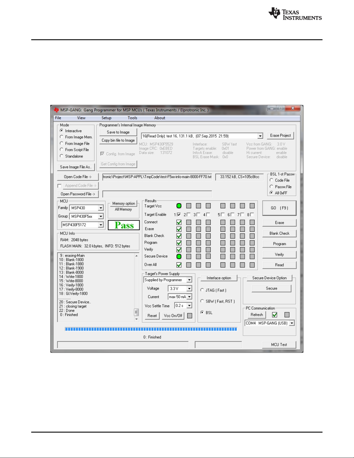
installation. Figure 2-1 shows the MSP Gang Programmer GUI in the Interactive Mode (see the Mode
group in the top left corner). This window is used to select the target microcontroller, code file used for
programming, power supply options, communication interface, and more. This window also shows the
result of programming and any errors, if they occur.
Figure 2-1. Main MSP Gang Programmer Dialog GUI, Interactive Mode
2. Select a target device using the MCU Family, then MCU Group, and then desired MCU Type.
3. Select the code file to be programmed into the devices using the Open Code File button or pulldown
menu: File→Open Code File. The formats supported for the code file are TI (.txt) and Intel (.hex) and
Motorola (.s19, .s28, .s37). Code size and checksum appear on the right side (for details on how the
checksum is calculated, see Section 2.1.13).
4. Optionally add another code file to be programmed into the devices using the Append Code File button
(check the box on the left to enable this option). This feature is useful for updating BSL firmware in 5xx
or 6xx MCUs. The two code files are combined together to create one final code file. If a conflict is