slau358q.pdf - 第38页
Programming MSP Flash Devices Using the MSP Gang Programmer www.ti.com 38 SLAU358Q – September 2011 – Revised October 2019 Submit Documentation Feedback Copyright © 2011–2019, Texas Instruments Incorporated Operation Whe…
www.ti.com
Programming MSP Flash Devices Using the MSP Gang Programmer
37
SLAU358Q–September 2011–Revised October 2019
Submit Documentation Feedback
Copyright © 2011–2019, Texas Instruments Incorporated
Operation
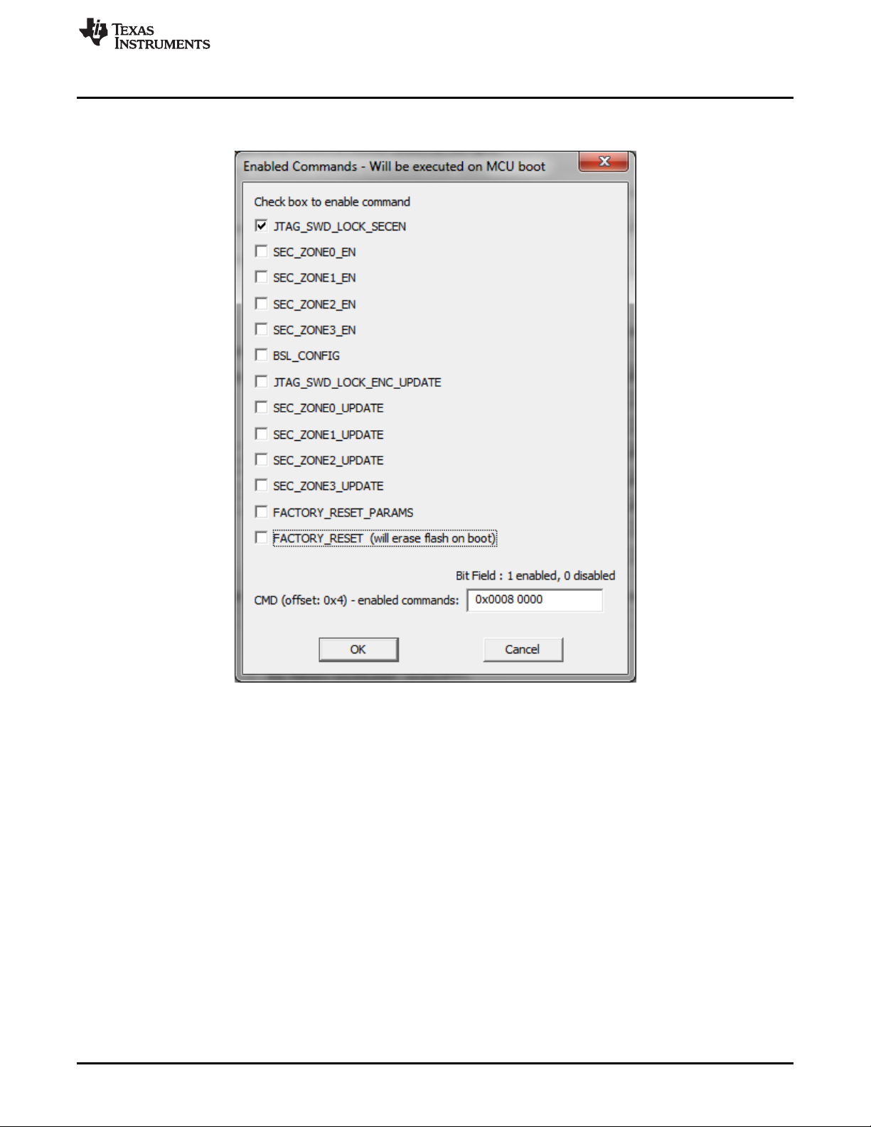
Many types of protection options are available and can be set in the Enabled Commands screen (see
Figure 2-15).
NOTE: The flash mailbox can be programmed with different instructions that provide memory protection, or block
communication.
Figure 2-15. MSP432 Secure Device Options Details
2.1.7 Programming MCU With IP Encapsulated Segment
Some FRAM MCUs have the option to protect an address range in main memory. All data from protected
memory space is read as 0x3FFF regardless of actual contents. When the protected memory is not
locked, then the contents can be read "as is" if the option "Including Unlocked MPU-IPE" is selected. The
programmer must have the address range of protected memory to be able to service the MCU correctly.
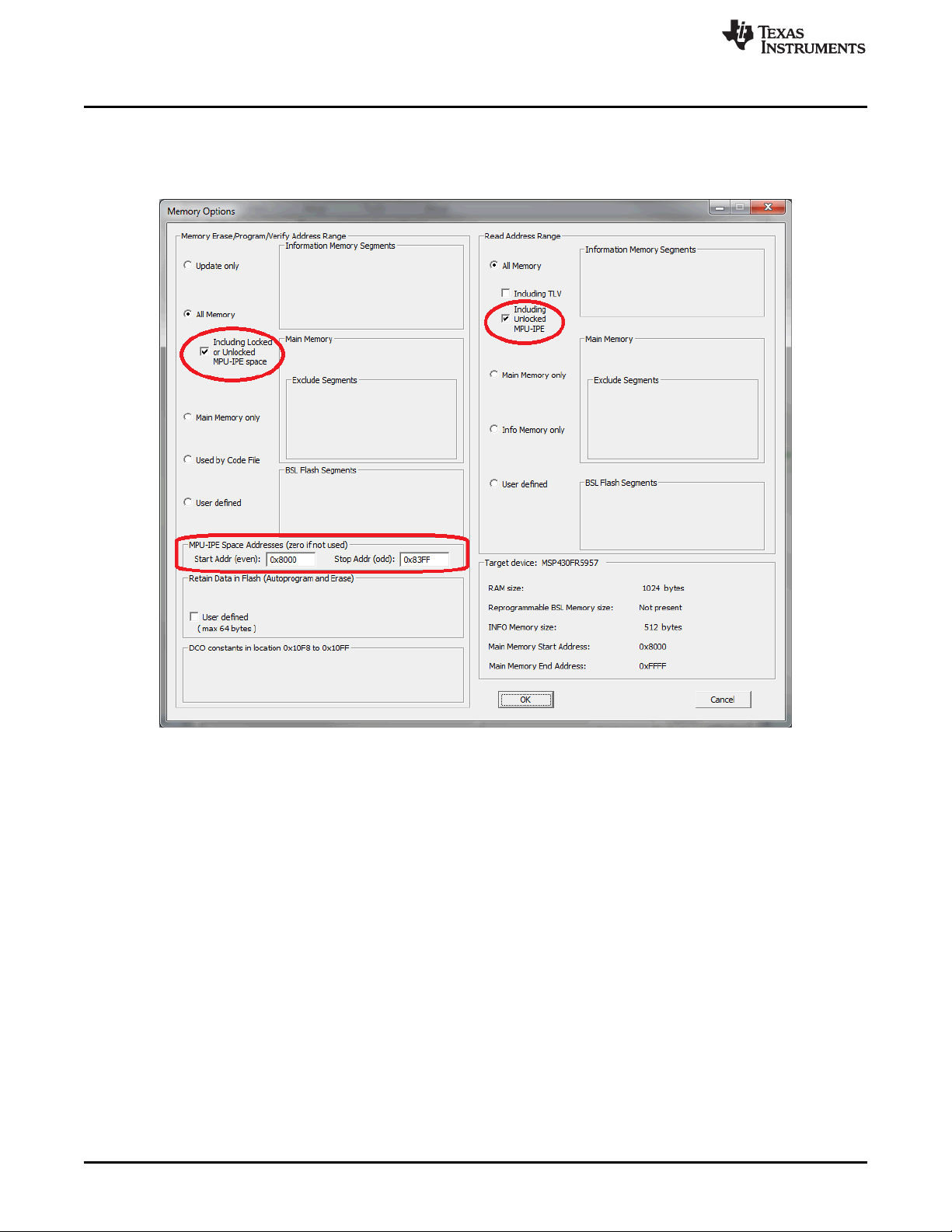
The protected memory range must be specified in the MPU-IPE Space Addresses Group in the Memory
Options window (see Figure 2-16). The protected memory space can be erased and reprogrammed when
the option "Including Locked or Unlocked MPU-IPE space" is selected. That option can only be selected
when the All Memory option is selected. When the memory region is protected and locked using the MPU-
IPE features (see MCU family user guide or technical reference manual for details) then all memory is
erased first before programming the MCU. The protected and locked MPU-IPE memory range can be
erased and reprogrammed only when the JTAG or SBW communication is used. When BSL
communication is used, the locked memory cannot be erased or reprogrammed. Through BSL, memory
can only be erased and reprogrammed when the locking option is not used.
Programming MSP Flash Devices Using the MSP Gang Programmer
www.ti.com
38
SLAU358Q–September 2011–Revised October 2019
Submit Documentation Feedback
Copyright © 2011–2019, Texas Instruments Incorporated
Operation
When a new code file is programmed with contents outside of the protected area, all memory (except
protected memory) can be erased, blank checked, programmed, and verified. If the protected memory
space is defined incorrectly, a blank check error will result, because 0x3FFF will be read instead of the
expected 0xFFFF.
Figure 2-16. Memory Options Window
2.1.8 Serialization
Serialization implemented in the MSP-GANG creates a unique serial number (SN) or MAC address and
saves it in the flash, FRAM, or dedicated MAC register in the target device. The SN or MAC address is
new every time a new target device is programmed. The SN or MAC number can be generated
automatically (incremented from the last number) or read from an external file every time before pressing
the GO button.
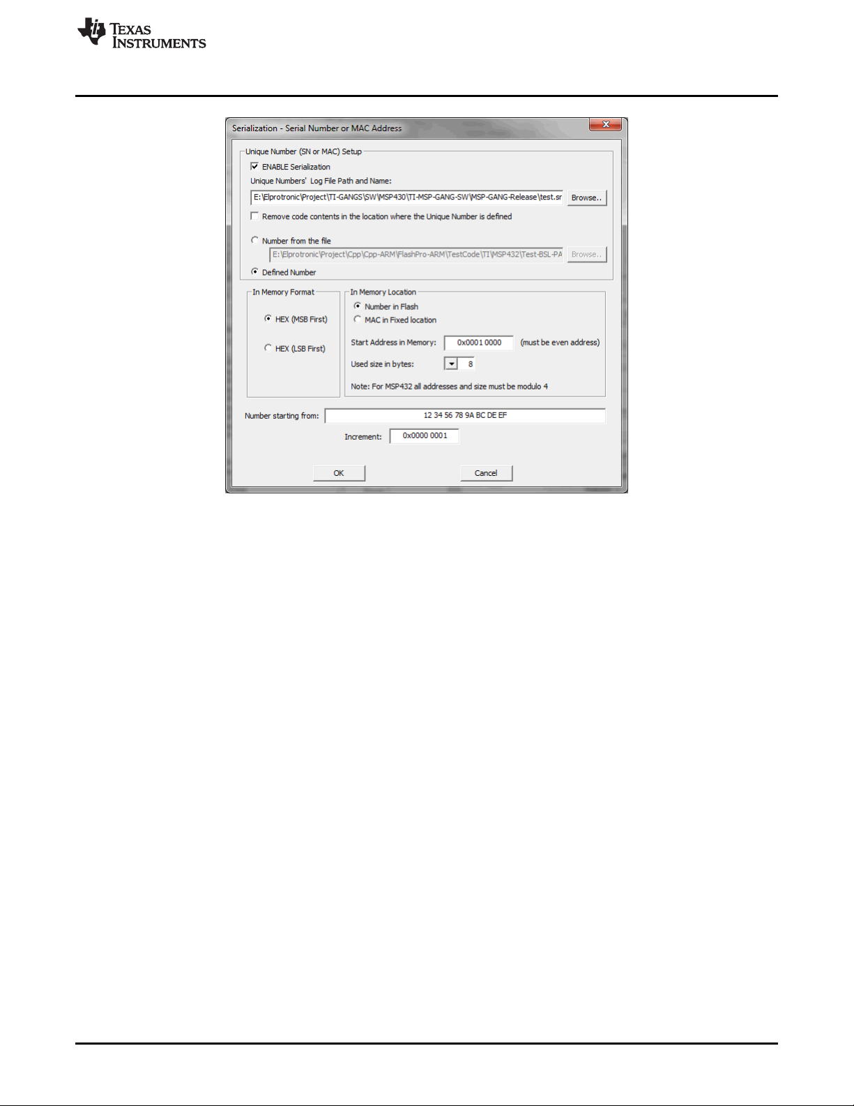
To enable serialization, select ENABLE Serialization in the Serialization screen (see Figure 2-17). Specify
the log file name where the all programmed SN and MAC numbers are saved. The SN or MAC number
can be saved in any flash or FRAM location as specified in the Start Address in Memory field (see
Figure 2-17). The address must be even, and the Used size in bytes (the size of the SN or MAC number)
must also be an even number of bytes. The In Memory Format section specifies if the SN or MAC number
is written LSB first or MSB first.
www.ti.com
Programming MSP Flash Devices Using the MSP Gang Programmer
39
SLAU358Q–September 2011–Revised October 2019
Submit Documentation Feedback
Copyright © 2011–2019, Texas Instruments Incorporated
Operation
Figure 2-17. Serialization
If the In Memory Format option is HEX (MSB First), the SN is saved to flash memory starting from the
specified address (0x10000) as follows:
12 34 56 78 9A BC DE EF
If the In Memory Format option is HEX (LSB First), the SN is saved to flash memory as follows:
EF DE BC 9A 78 56 34 12
In the report window and log file, the SN is always displayed in the same order as it is saved in memory
starting from the lowest address to the highest. In this case, if the SN is saved in memory as MSB first,
then the displayed SN in the report window, log file, and Serialization screen (see Figure 2-17) are the
same.
If the SN or MAC number is generated automatically (the Defined Number option is selected), the number
is generated starting with the value in the Number starting from field and incremented as specified in the
Increment field. All numbers must be specified in hex format. When the target are programmed with the
new numbers, the value in Number starting from is automatically updated and saved in the configuration
for use in the next session. The user is responsible for tracking whether or not a particular SN or MAC
number has been used. The programmer only applies the values set by the user.
When the Number from the file option is selected, up to 8 numbers (SN or MAC) must be in the user-
specified file, which must have an extension of .txt. The file can contain up to 8 numbers that will be
applied in the next programming session. The file must be saved and valid before the GO button is
pressed. If additional targets are to be programmed, the file must be updated with the new number list.
The following list is an example of the contents of the SN or MAC number file:
01 0A A3 B4 32 35 65 23
01 0A A3 B4 32 35 65 24
01 0A A3 B4 32 35 65 25
01 0A A3 B4 32 35 65 26
01 0A A3 B4 32 35 65 27
01 0A A3 B4 32 35 65 28
01 0A A3 B4 32 35 65 29
01 0A A3 B4 32 35 65 2A