slau358q.pdf - 第39页
www.ti.com Programming MSP Flash Devices Using the MSP Gang Programmer 39 SLAU358Q – September 2011 – Revised October 2019 Submit Documentation Feedback Copyright © 2011–2019, Texas Instruments Incorporated Operation Fig…
Programming MSP Flash Devices Using the MSP Gang Programmer
www.ti.com
38
SLAU358Q–September 2011–Revised October 2019
Submit Documentation Feedback
Copyright © 2011–2019, Texas Instruments Incorporated
Operation
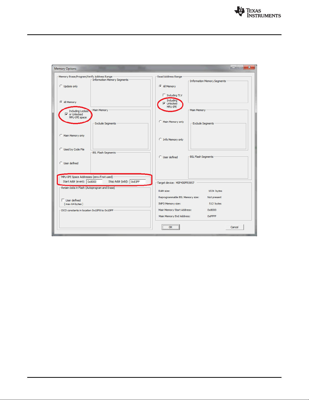
When a new code file is programmed with contents outside of the protected area, all memory (except
protected memory) can be erased, blank checked, programmed, and verified. If the protected memory
space is defined incorrectly, a blank check error will result, because 0x3FFF will be read instead of the
expected 0xFFFF.
Figure 2-16. Memory Options Window
2.1.8 Serialization
Serialization implemented in the MSP-GANG creates a unique serial number (SN) or MAC address and
saves it in the flash, FRAM, or dedicated MAC register in the target device. The SN or MAC address is
new every time a new target device is programmed. The SN or MAC number can be generated
automatically (incremented from the last number) or read from an external file every time before pressing
the GO button.
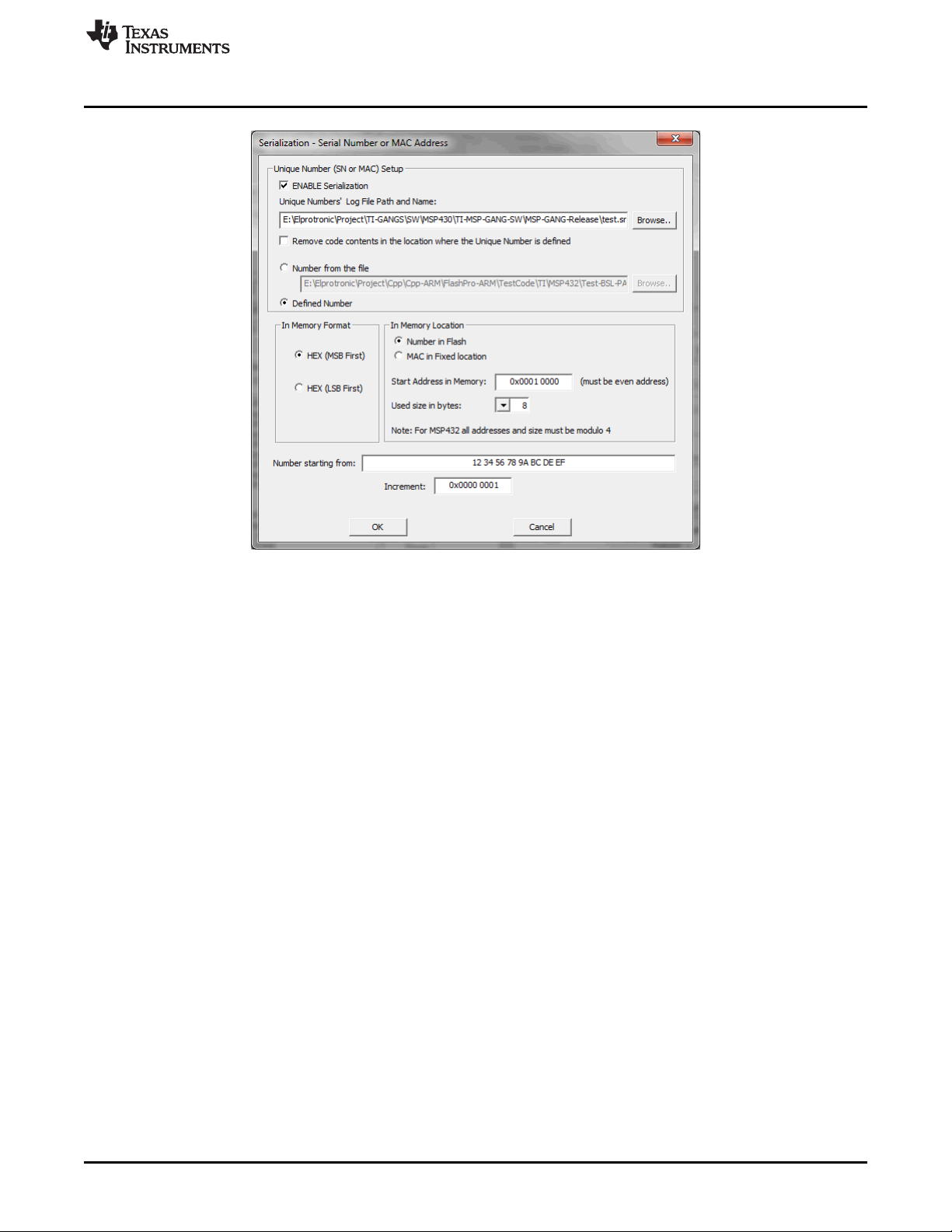
To enable serialization, select ENABLE Serialization in the Serialization screen (see Figure 2-17). Specify
the log file name where the all programmed SN and MAC numbers are saved. The SN or MAC number
can be saved in any flash or FRAM location as specified in the Start Address in Memory field (see
Figure 2-17). The address must be even, and the Used size in bytes (the size of the SN or MAC number)
must also be an even number of bytes. The In Memory Format section specifies if the SN or MAC number
is written LSB first or MSB first.
www.ti.com
Programming MSP Flash Devices Using the MSP Gang Programmer
39
SLAU358Q–September 2011–Revised October 2019
Submit Documentation Feedback
Copyright © 2011–2019, Texas Instruments Incorporated
Operation
Figure 2-17. Serialization
If the In Memory Format option is HEX (MSB First), the SN is saved to flash memory starting from the
specified address (0x10000) as follows:
12 34 56 78 9A BC DE EF
If the In Memory Format option is HEX (LSB First), the SN is saved to flash memory as follows:
EF DE BC 9A 78 56 34 12
In the report window and log file, the SN is always displayed in the same order as it is saved in memory
starting from the lowest address to the highest. In this case, if the SN is saved in memory as MSB first,
then the displayed SN in the report window, log file, and Serialization screen (see Figure 2-17) are the
same.
If the SN or MAC number is generated automatically (the Defined Number option is selected), the number
is generated starting with the value in the Number starting from field and incremented as specified in the
Increment field. All numbers must be specified in hex format. When the target are programmed with the
new numbers, the value in Number starting from is automatically updated and saved in the configuration
for use in the next session. The user is responsible for tracking whether or not a particular SN or MAC
number has been used. The programmer only applies the values set by the user.
When the Number from the file option is selected, up to 8 numbers (SN or MAC) must be in the user-
specified file, which must have an extension of .txt. The file can contain up to 8 numbers that will be
applied in the next programming session. The file must be saved and valid before the GO button is
pressed. If additional targets are to be programmed, the file must be updated with the new number list.
The following list is an example of the contents of the SN or MAC number file:
01 0A A3 B4 32 35 65 23
01 0A A3 B4 32 35 65 24
01 0A A3 B4 32 35 65 25
01 0A A3 B4 32 35 65 26
01 0A A3 B4 32 35 65 27
01 0A A3 B4 32 35 65 28
01 0A A3 B4 32 35 65 29
01 0A A3 B4 32 35 65 2A

Programming MSP Flash Devices Using the MSP Gang Programmer
www.ti.com
40
SLAU358Q–September 2011–Revised October 2019
Submit Documentation Feedback
Copyright © 2011–2019, Texas Instruments Incorporated
Operation
The preceding example lists numbers that would be programmed to 8 target devices using a size of 8
bytes each. These hex numbers can represent integer values or ASCII text, depending on the application.
In the case of ASCII, the text must be converted to hex in the file.
After a set of 8 targets is programmed, the user must update the file (the same file name) with new
values. The following example lists a new set of 8 values:
01 0A A3 B4 32 35 65 2B
01 0A A3 B4 32 35 65 2C
01 0A A3 B4 32 35 65 2D
01 0A A3 B4 32 35 65 2E
01 0A A3 B4 32 35 65 2F
01 0A A3 B4 32 35 65 30
01 0A A3 B4 32 35 65 31
01 0A A3 B4 32 35 65 32
The programmer writes the numbers as provided to the specified flash or FRAM location. The provided
numbers must be the same size (in bytes) as specified in the Used size in bytes option (see Figure 2-17).
The SN or MAC number can be also saved to a dedicated register, if available on the target MCU; for
example, in the MSP432E4xx MCUs. In this case, select the MAC in Fixed location option. The address
for the MAC number is hardcoded and displayed (read only and grayed out) for user review in the Start
Address in Memory field (see Figure 2-17).
If the SN or MAC number is saved to flash or FRAM, the same address cannot be used by the program
code (specified in the code file). The programmer will display a warning if it detects a conflict between
address of the SN or MAC number and code. If the linker requires that the code file fill the SN or MAC
number location with a dummy value, select the Remove code contents in the location where the Unique
Number is defined option to overwrite this location with the correct SN or MAC number.
If location specified for the SN or MAC number is not empty (all 0xFF), the SN or MAC number is not
written to the target. If the programmer detects any value other that 0xFF, the existing value is restored
and the new SN or MAC number is ignored. This process keeps an existing SN or MAC number in the
target if the number was already programmed. To overwrite an existing value, erase the device memory
before programming.
NOTE: The MSP-GANG does not erase the existing SN or MAC number if the erase all memory
option is used. The old SN or MAC number is restored after the erase, the same way that
the defined retained bytes are restored.
The SN or MAC number can be erased; for example, if serialization is disabled. After erasing, the SN or
MAC number location can be used as regular memory.
2.1.9 Creating and Using Images
An image contains the code files and the configuration options necessary for programming of a target
device. Images can be stored as a binary file (".mspgangbin") in internal MSP Gang Programmer memory
(or SD card), or as an image file (".mspgangimage") on disk for redistribution. Image files intended for
redistribution can be encrypted with additional security features described later in this section.
Creating an image is done in Interactive Mode by following the same steps described in Section 2.1.4,
followed by pressing the "Save Image File As…" or "Save to Image" buttons. The first button saves the
code files and configuration options as a binary file and image file locally on disk, and the second button
saves this information directly to the MSP Gang Programmer internal memory. Note that to use the MSP
Gang Programmer in Standalone mode, you need to program at least one image to internal memory or
read a binary file from an SD card (using the SD card connector on the MSP Gang Programmer). If you
intend to modify the contents of an image at a later date, it is advisable to save the configuration options
as a project. Because an image is read-only, reading a project file is the only way to recreate images
easily without reentering the configuration options from scratch. After the project is loaded, a change can
be made and a new image with the same name can be created to overwrite the previous one.