slau358q.pdf - 第65页
www.ti.com Command Messages 65 SLAU358Q – September 2011 – Revised October 2019 Submit Documentation Feedback Copyright © 2011–2019, Texas Instruments Incorporated Firmware The following abbreviations are used in Table 3…

Firmware Interface Protocol
www.ti.com
64
SLAU358Q–September 2011–Revised October 2019
Submit Documentation Feedback
Copyright © 2011–2019, Texas Instruments Incorporated
Firmware
3.2 Firmware Interface Protocol
The MSP Gang Programmer supports a UART communication protocol at baud rates from 9.6 to 115.2
kbaud in half duplex mode. The default baud rate at startup is 9.6 kbaud. This allows for communication
between the MSP Gang Programmer and devices that have a lower communication speed than the
maximum 115.2 kbaud. It is recommended that after startup the communication speed be increased to the
common maximum for both devices to enable faster communication. If the control device has a USB
interface with a virtual COM port, then it is recommended to use USB for communication between the
control device and the MSP Gang Programmer, because USB is several times faster than RS-232.
Communication requires one start bit, eight data bits, even parity bit, and one stop bit. A software
handshake is performed by a (not) acknowledge character.
3.3 Synchronization Sequence
To synchronize with the MSP-GANG Programmer the host serial handler transmits a SYNC (CR)
character (0x0D) to the MSP-GANG Programmer. The MSP-GANG Programmer acknowledges successful
reception of the SYNC character by responding with a DATA ACK character (0x90). If the SYNC is not
received correctly, no data is sent back. This sequence is required to establish the communication
channel and to react immediately to line faults. The synchronization character is not part of the data frame
described in Section 3.4.1. When communication is established, the synchronization character is not
required any more, but it can be send at any time for checking the "alive" status if required.
The synchronization character is not part of the data frame described in Section 3.4.1.
3.4 Command Messages
The MSP-GANG has a few type of messages with mandatory responses for each received command.
• Short TX messages with one byte only
"Hello"
Tx -> 0x0d (CR)
Rx -> 0x90 (ACK)
Get Progress Status
Tx -> 0xA5
Rx -> 0x80 0x00 <...data...> (without Check Sum)
• Standard TX messages with data frame
Tx -> 0xA5
Rx -> 0x80 0x00 <...data...> (without Check Sum)
3.4.1 Frame Structure
The data frame format follows the TI MSP serial standard protocol (SSP) rules, extended with a preceding
synchronization sequence (SS), as described in Section 3.3. The MSP Gang Programmer is considered
the receiver in Table 3-1, which details the data frame for firmware commands. The redundancy of some
parameters results from the adaptation of the SSP or to save boot ROM space.
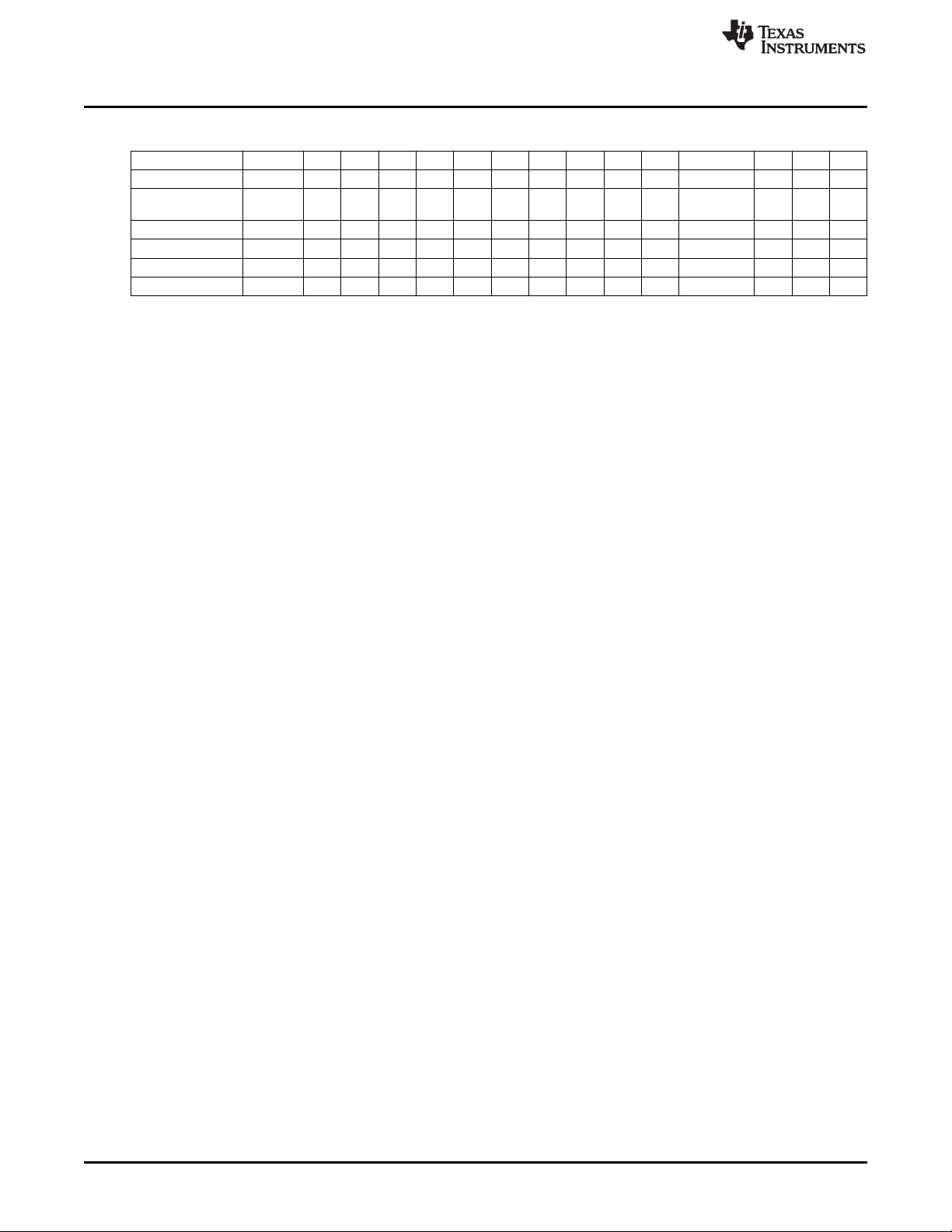
The data frame format of the firmware commands is shown in Table 3-1.
• The first eight bytes (HDR through LH) are mandatory (– represents dummy data).
• Data bytes D1 to Dn are optional.
• Two bytes (CKL and CKH) for checksum are mandatory
• Acknowledge done by the MSP Gang Programmer is mandatory.

www.ti.com
Command Messages
65
SLAU358Q–September 2011–Revised October 2019
Submit Documentation Feedback
Copyright © 2011–2019, Texas Instruments Incorporated
Firmware
The following abbreviations are used in Table 3-1.
CMD Command identification
R Do not use this command. Used for internal communication.
T Target number (1 to 8)
L1, L2 Number of bytes in AL through Dn. The valid values of these bytes are restricted as follows: L1 = L2, L1 < 255, L1 even.
A1, A2, A3 Block start address or erase (check) address or jump address LO or HI byte. The bytes are combined to generate a 24-bit word as follows: Address = A3 × 0x10000 + A2 × 0x100 + A1
LL, LH Number of pure data bytes (maximum 250) or erase information LO or HI byte or block length of erase check (max is 0xFFFF).
D1...Dn Data bytes
CKL, CKH 16-bit checksum LO or HI byte
xx Can be any data
– No character (data byte) received or transmitted
ACK The acknowledge character returned by the MSP-GANG can be either DATA_ACK = 0x90 (frame was received correctly, command was executed successfully) or DATA_NAK = 0xA0 (frame not valid (for example, wrong checksum, L, L2), command is
not defined, is not allowed.
PRS DATA_IN_PROGRESS = 0xB0 – Tasks in progress. Use Get Progress Status (0xA5) command to get the status and check when task is finished.
(1)
All numbers are bytes in hexadecimal notation. ACK is sent by the MSP-GANG.
(2)
PROMPT = 0x3E means data frame expected.
Table 3-1. Data Frame for Firmware Commands
(1) (2)
MSP-GANG
Firmware
Command
PROMPT CMD L1 L2 A1 A2 A3 A4 LL LH D1 D2...Dn CLK CLH ACK
"Hello" 0D – – ACK
Boot Commands
Disable
3E 2A R R R R R R R R R R CKL CKH ACK
Boot Commands
Enable
3E 2B R R R R R R R R R R CKL CKH ACK
Diagnostic 3E 32 04 04 00 00 – – 00 00 – – CKL CKH –
Diagnostic response 80 0 1E 1E D1 D2 D3 D4 D5 D6 D7 D08...D1E CKL CKH –
Set Baud Rate 3E 38 06 06 D1 00 – – 00 00 00 00 CKL CKH ACK
Erase Firmware 3E 39 R R R R R R R R R R CKL CKH ACK
Load Firmware 3E 3A R R R R R R R R R R CKL CKH ACK
Exit Firmware
Update
3E 3B R R R R R R R R R R CKL CKH ACK
Get Label 3E 40 04 04 00 00 – – 00 00 – – CKL CKH –
Response-Get Label 80 00 8C 8C D1 D2 D3 D4 D5 D6 D7 D8...D140 CKL CKH –
Get Progress Status A5 – –
Response----,,,,--- 80 A5 D1 D2 D3 D4 D5 D6 D7 D7 D8 D9...D48 – –
Main Process 3E 31 04 04 00 00 – – 00 00 – – CKL CKH PRS
Interactive Task 3E 46 n n D1 D2 – – D3 D4 D5 D6...Dn CKL CKH –
Response---,,--- 80 0 n n D1 D2 D3 D4 D5 D6 D7 D8...Dn CKL CKH –
Erase Image 3E 33 04 04 00 00 – – 00 00 – – CKL CKH PRS
Get Info C-D 3E 41 04 04 A1 00 – – 00 00 – – CKL CKH –
Response Get Info 80 0 80 80 D1 D2 D3 D4 D5 D6 D7 D8...D128 CKL CKH
Write Info C-D 3E 42 84 84 A1 00 80 0 D1 D2...D128 CKL CKH ACK
Get Access Key St 3E 44 04 04 00 00 – – 00 00 – – CKL CKH ACK
Load Image 3E 43 n n A1 A2 A3 00 –6 00 D1 D2...Dn-6 CKL CKH ACK
Verify Image CRC 3E 45 08 08 A1 A2 A3 A4 LL LH D1 D2 CKL CKH ACK
Get Image Header 3E 47 06 06 A1 A2 00 00 n 00 – – CKL CKH –
Response–,,,-- 80 0 n n D1 D2 – – D3 D4 D5 D6...Dn CKL CKH
Read Gang Buffer 3E 49 4 4 T 0 – – n 0 – – CKL CKH –
Response–,,,-- 80 0 n n D1 D2 D3 D4 D5 D6 D7 D8...Dn CKL CKH
Write Gang Buffer 3E 4A n+4 n+4 T 0 – – n 0 D1 D2...Dn CKL CKH ACK
Disable API
Interrupts
3E 4C 4 4 R R – – R R – – CKL CKH ACK
Select Image 3E 50 4 4 A1 0 – – 0 0 CKL CKH ACK
Command Messages
www.ti.com
66
SLAU358Q–September 2011–Revised October 2019
Submit Documentation Feedback
Copyright © 2011–2019, Texas Instruments Incorporated
Firmware
Table 3-1. Data Frame for Firmware Commands
(1) (2)
(continued)
Display Message 3E 54 n+4 n+4 A1 A2 – – n 00 D1 D2...Dn CKL CKH ACK
Set IO State 3E 4E 0C 0C VL VH – – 08 00 D1 D2...D8 CKL CKH ACK
Set Temporary
Configuration
3E 56 06 06 A1 A2 – – 2 0 D1 D2 CKL CKH ACK
Get Gang Status 3E 58 04 04 A1 0 – – 0 0 – – CKL CKH –
Response —,,,--- 80 0 n n D1 D2 D3 D4 D5 D6 D7 D8...Dn CKL CKH
Remote Selftest 3E 71 n+6 n+6 A1 A2 A3 A4 n 0 D1 D2...Dn CKL CKH
Response----,,--- 80 0 n n D1 D2 D3 D4 D5 D6 D7 D8...Dn CKL CKH
3.4.2 Checksum
The 16-bit (2-byte) checksum is calculated over all received or transmitted bytes, B1 to Bn, in the data
frame except the checksum bytes themselves. The checksum is calculated by XORing words (two
consecutive bytes) and bit-wise inverting (∼) the result, as shown in the following formulas.
CHECKSUM = INV [ (B1 + 256 × B2) XOR (B3 + 256 × B4) XOR...XOR ((Bn – 1) + 256 × Bn) ]
or
CKL = INV [ B1 XOR B3 XOR...XOR Bn–1 ]
CKH = INV [ B2 XOR B4 XOR...XOR Bn ]
An example of a frame for the Execute Self Test command with checksum would appear as:
0x3E 0x35 0x06 0x06 0x00 0x00 0x00 0x00 0x00 0x00 0xC7 0xCC
3.5 Detailed Description of Commands
3.5.1 General
After the prompt byte (0x3E) and the command identification byte CMD, the frame length bytes L1 and L2
(which must be equal) hold the number of bytes following L2, excluding the checksum bytes CKL and
CKH. Bytes A1, A2, A3, A4, LL, LH, and D1 to Dn are command specific. However, the checksum bytes
CKL (low byte) and CKH (high byte) are mandatory. If the data frame is received correctly and the
command execution is successful, the acknowledge byte ACK (0x90), in progress byte (0xB0) or received
message with header byte (0x80) as the first one. Incorrectly received data frames, unsuccessful
operations, and commands that are not defined are confirmed with a DATA_NACK = 0xA0.
3.5.2 Commands Supported by the BOOT Loader
3.5.2.1 "Hello" Command
Short TX messages with one byte only
Tx -> 0x0d (CR)
Rx -> 0x90 (ACK)
A response is sent only when the <CR> (0x0D byte) has been detected and when it is not the byte used
as the part of the data frame. This command can be useful for checking communication with the MSP-
GANG. When there is no response, then the baud rate should be changed. After power-up, the USB
interface is used for communication with the MSP GANG; however, the RS-232 receiver is also active. To
reestablish communication between USB and RS-232, the "Hello" command must be sent a minimum of
three times through RS-232. After this, an ACK (0x90) is transmitted through RS-232. This sequence also
works in reverse, to reestablish communication between RS-232 and USB.