03238396-01-01 High Flow Vacuum (TQ).pdf - 第14页
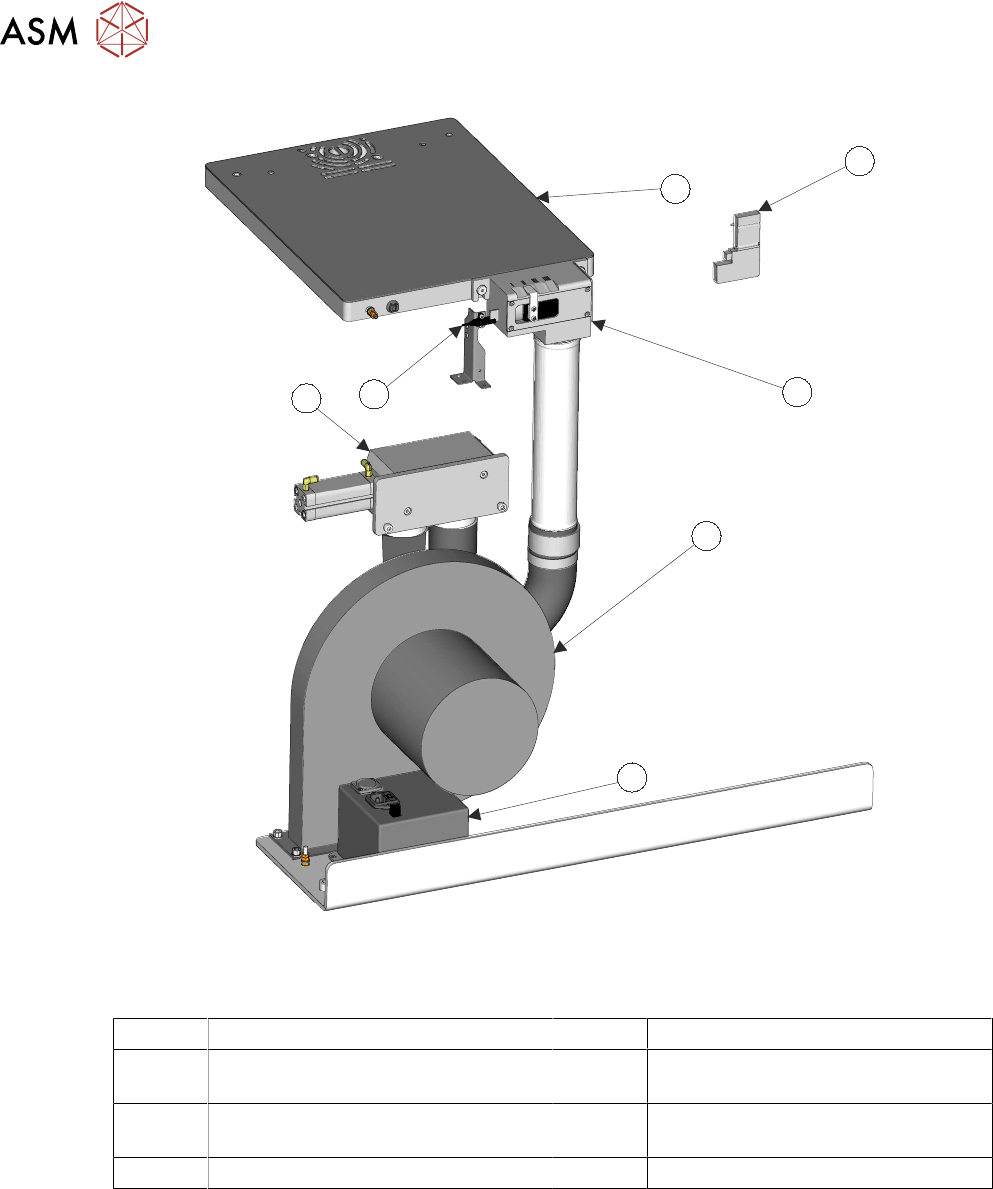
5 TECHNICAL REFERENCE 5.1 SYSTEM OVERVIEW 14 STANDALONE MANUAL HIGH FLOW VACUUM (TQ) 12/2020 1 2 6 5 7 3 4 High Flow Vacuum System – viewed from the rear of the printer 1 Solenoid 1SOL4 5 Vacuum Pump Enable Enclosure 2 T…

5 TECHNICAL REFERENCE
5.1 SYSTEM OVERVIEW
STANDALONE MANUAL HIGH FLOW VACUUM (TQ) 12/2020 13
5
TECHNICAL REFERENCE
5.1 SYSTEM OVERVIEW
The High Flow Vacuum system allows the printer to use low-cost flexible tooling with a high flow–
low pressure vacuum capability.
Bespoke board support tooling plates form a vacuum chamber around the perimeter of the product
or carrier. A table-mounted Tooling Plate assembly is secured to the existing rising table. A pump
provides the vacuum pressure. The option to switch the vacuum on or off is provided in software, it
controls the Vacuum Diverter Valve operation. In the ON state the system is placed under vacuum,
in the OFF state the vacuum is diverted to a port that vents the vacuum. The flow controller valve
allows the user to manually set a vacuum flow level by operating a variable aperture. The three op-
erational states are:
●
High flow vacuum OFF
●
High flow vacuum OFF during the Print Stroke
●
High flow vacuum ON
Unless disabled in the program file, the pump runs continuously during printing.
Key system components:
●
Pump
●
Bespoke Magnetic Board Support Tooling (not shown)
●
Tooling Plate
●
Flow Controller Valve
●
Vacuum Diverter Valve
5 TECHNICAL REFERENCE
5.1 SYSTEM OVERVIEW
14 STANDALONE MANUAL HIGH FLOW VACUUM (TQ) 12/2020
1
2
6
5
7
3
4
High Flow Vacuum System – viewed from the rear of the printer
1 Solenoid 1SOL4 5 Vacuum Pump Enable Enclosure
2 Table-Mounted Tooling Plate
Assembly
6 Diverter Valve
3 Flow Controller Valve 7 High Flow Vacuum Fitted Sensor
(table at home)
4 Vacuum Pump
5 TECHNICAL REFERENCE
5.1 SYSTEM OVERVIEW
STANDALONE MANUAL HIGH FLOW VACUUM (TQ) 12/2020 15
5.1.1 Mechanical Assemblies
5.1.1.1 Tooling Plate
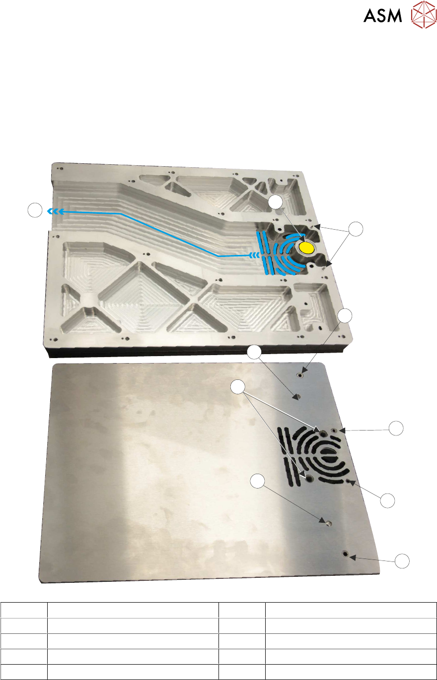
The tooling plate is fitted to the printer table and forms an interface with the product support tooling.
The tooling plate is constructed in two parts; the base (first image, viewed from underneath) and
the surface plate (second image), are bonded together,
The vacuum is pulled along a channel (10) in the base of the tooling table to the tooling table sur-
face plate.
1
2
3
4
5
6
7
8
9
10
2
1 Venturi Vacuum Port 6 4mm Plain Bush
2 Tooling Table Location Dowels 7 Hole for M4 x 40 Securing Screw
3 4mm Slotted Bush 8 6mm Plain Bush
4 3mm Slotted Bush 9 Hole for M4 x 40 Securing Screw
5 3mm Plain Bush 10 Vacuum Channel
Two dowel pins (2) on the tooling plate align with the holes on the printer table.
Once placed on the rising table the tooling plate is held in place with two M4 x 40 screws (7&9).
The remaining bushed holes correspond to those on the printer table and are used for tooling
placement.