03238396-01-01 High Flow Vacuum (TQ).pdf - 第30页
5 TECHNICAL REFERENCE 5.4 REPLACEMENT PROCEDURES 30 STANDALONE MANUAL HIGH FLOW VACUUM (TQ) 12/2020 5.4.4 Diverter Valve Sensors Two solid state Reed switches are located on the body of the actuator: ● Diverter Valve Ret…
5 TECHNICAL REFERENCE
5.4 REPLACEMENT PROCEDURES
STANDALONE MANUAL HIGH FLOW VACUUM (TQ) 12/2020 29
12. Switch the printer ON and test.
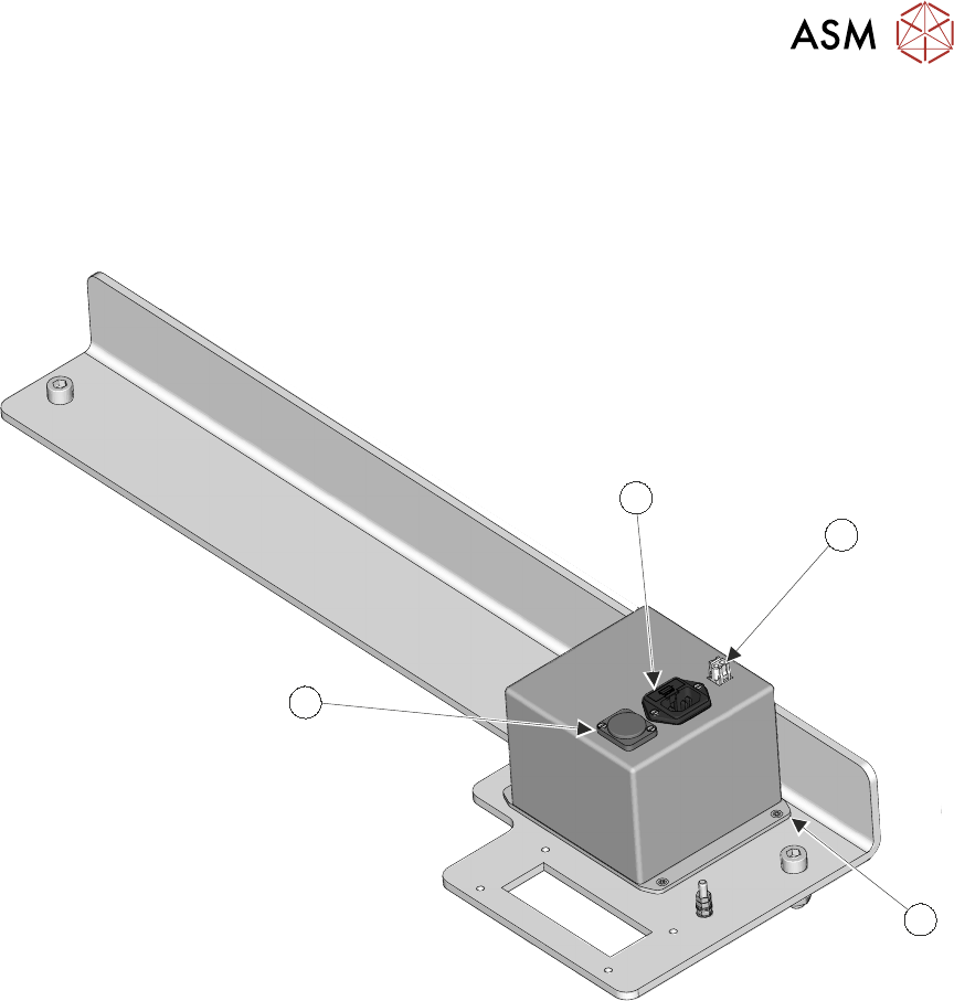
5.4.3 Vacuum Pump Enable Controller (VPEC)
The vacuum pump enable controller (VPEC) enclosure is a complete item replacement. There are
no user serviceable parts.
1
2
3
4
1. On the printer’s front cover, turn the mains isolator switch to OFF and lockout the switch.
2. Gain access to the assembly by removing the lower rear panel.
3. Remove the mains cable from the socket (4).
4. Remove the mains cable from the plug (1).
5. Remove the signal cable from the socket (2).
6. Remove the four M4 x 8 counter-sunk head screws (3) using an 3mm Allen key.
7. Lift the enclosure clear of the support bracket.
8. Replacement is the reverse of the removal procedure.
9. Replace the printer’s lower rear panel.
10. Remove the lockout from the printer’s mains isolator and switch the printer ON.
5 TECHNICAL REFERENCE
5.4 REPLACEMENT PROCEDURES
30 STANDALONE MANUAL HIGH FLOW VACUUM (TQ) 12/2020
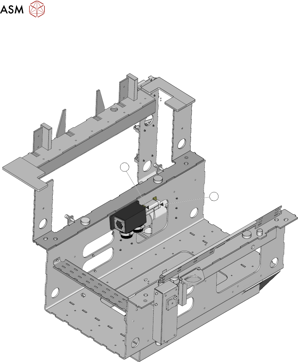
5.4.4 Diverter Valve Sensors
Two solid state Reed switches are located on the body of the actuator:
●
Diverter Valve Retracted Sensor 2SE11 (1)
●
Diverter Valve Extended Sensor 2SE10 (2)
1
2
Before removing the diverter valve refer to 5.3.1 "Diverter Valve Sensors Test" [}21] section.
5 TECHNICAL REFERENCE
5.4 REPLACEMENT PROCEDURES
STANDALONE MANUAL HIGH FLOW VACUUM (TQ) 12/2020 31
To replace the diverter valve position sensors:
1
1. Turn the mains isolator switch to OFF and lockout the switch.
2. Remove the front panel.
3. Turn the Safety Lockout Switch, located on the Pneumatic Regulator, to the EXH position.
4. Fit a suitable locking device to the switch to prevent air being accidently applied.
5. Remove the vacuum pump and hoses as detailed previously in this section.
NOTE
Remove the hose ends only from the diverter valve hose connectors: items 1 and 4 in the
hose removal procedure above.
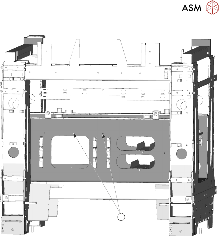
6. At the bulkhead locate the two M6 x 14 fixing screws (1).
7. Loosen the two screws, using a 5mm Allen key, whilst supporting the diverter valve (through
the access hole in the bulkhead panel).
8. Completely remove the screws and the diverter valve.