03238396-01-01 High Flow Vacuum (TQ).pdf - 第20页
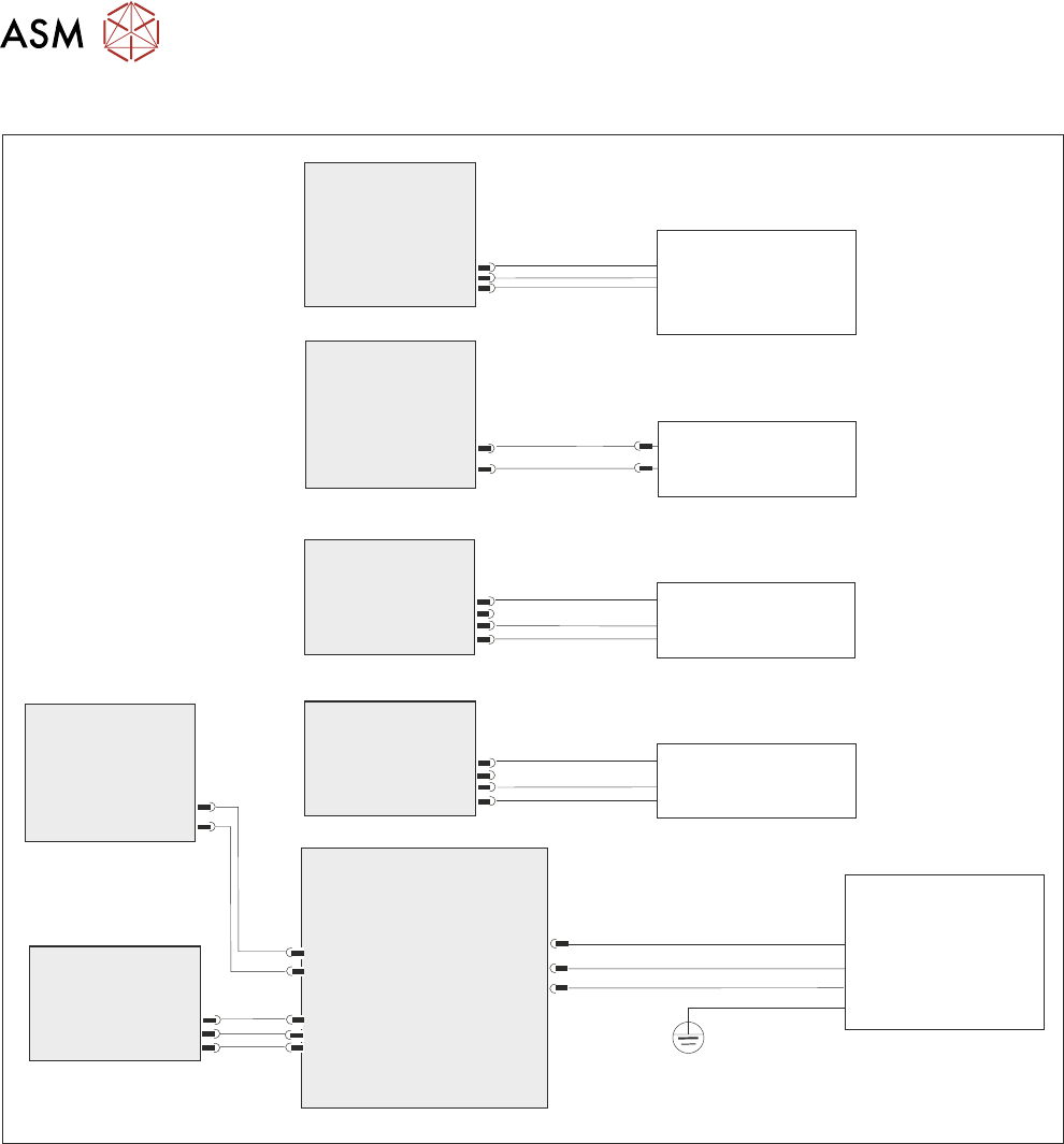
5 TECHNICAL REFERENCE 5.2 ELECTRICAL SCHEMATIC 20 STANDALONE MANUAL HIGH FLOW VACUUM (TQ) 12/2020 5.2 ELECTRICAL SCHEMATIC Breakout A Part ESIO #1 Part ESIO #2 Part ESIO #2 Breakout A Part ESIO #3 Part M71 PSU V ac Pump …

5 TECHNICAL REFERENCE
5.1 SYSTEM OVERVIEW
STANDALONE MANUAL HIGH FLOW VACUUM (TQ) 12/2020 19
At the pump’s vacuum input port, a magnetic coupling (7) is used to connect to the diverter valve
air hose.
The pump and VPEC unit are mounted onto the printer’s chassis with a mounting plate beam (2).
5.1.2 Operational Sequence
With High Flow Vacuum fitted and enabled, the print sequence is as follows:
1. Print is selected.
2. High Flow Vacuum is switched ON and remains on.
3. The product is loaded; the carrier/board moves into the print station and stops at the remote
board stop and is clamped.
4. The product is raised to vision height.
5. Camera sweep occurs to collect substrate and stencil fiducials data.
6. Align chase/stencil is performed.
7. The product is raised to print height.
8. The product is printed.
9. Separate the product from the stencil.
10. The product is lowered to vision height.
11. Camera sweep (post print alignment) is performed.
12. Table moves to transport height -unload product at transport height.
13. Carrier/board moves to outroad conveyor.
14. The sequence repeats from step 3 until the batch has printed.
15. High flow vacuum switches OFF.
5 TECHNICAL REFERENCE
5.2 ELECTRICAL SCHEMATIC
20 STANDALONE MANUAL HIGH FLOW VACUUM (TQ) 12/2020
5.2 ELECTRICAL SCHEMATIC
Breakout A
Part ESIO #1
Part ESIO #2
Part ESIO #2
Breakout A
Part ESIO #3
Part M71 PSU
Vac Pump Enable
Controller
BreakoutB
Part ESIO #1
1ASK13
2IO10
2IO11
5SK258
DIN 10
3APL27
Dout 7
M71PL34
8PL259
8PL260
DIN 09
1BSK25
PART
1SK6
+24V US
1BSK20
H F VAC
Present Sensor
1SE12
Table Present
Sensor
(Start Capacitor not shown)
Diverter Valve
Extended Sensor
2SE10
Diverter Valve
Retracted Sensor
2SE11
Tooling Vac Pump
HF VAC Diverter
Valve
1SOL4
L
N
E
5 TECHNICAL REFERENCE
5.3 TEST PROCEDURES
STANDALONE MANUAL HIGH FLOW VACUUM (TQ) 12/2020 21
5.3 TEST PROCEDURES
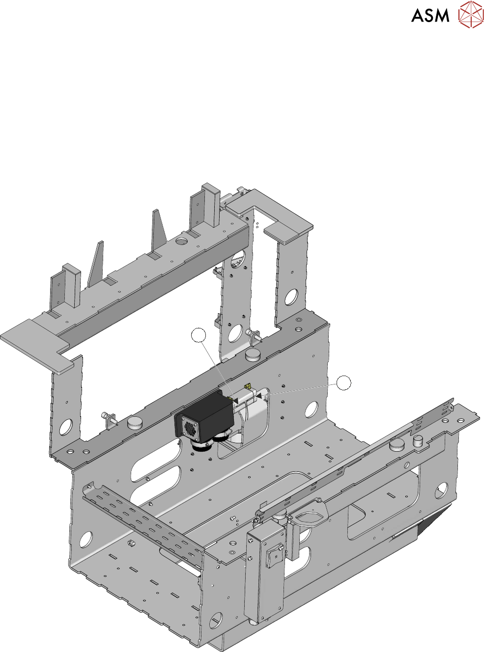
5.3.1 Diverter Valve Sensors Test
The diverter valve is mounted at the rear of the bulkhead. The pump assembly is located on the
front side of the bulkhead.
If viewed from the rear of the printer, a flexible hose from the pump connects to the left-hand port
on the diverter valve; the right-hand side hose connects to the riser pipe. Because of its physical
location, on the other side of the bulkhead, it is important to confirm that any fault lies with the di-
verter valve. To gain access to the sensors requires the removal of the pump, the hoses and the di-
verter valve.
1
2
Testing the sensors (this procedure requires two people):