03238396-01-01 High Flow Vacuum (TQ).pdf - 第16页
5 TECHNICAL REFERENCE 5.1 SYSTEM OVERVIEW 16 STANDALONE MANUAL HIGH FLOW VACUUM (TQ) 12/2020 5.1.1.2 Diverter Valve The diverter provides a means of rapidly venting the system vacuum whilst keeping the pump run- ning. Th…
5 TECHNICAL REFERENCE
5.1 SYSTEM OVERVIEW
STANDALONE MANUAL HIGH FLOW VACUUM (TQ) 12/2020 15
5.1.1 Mechanical Assemblies
5.1.1.1 Tooling Plate
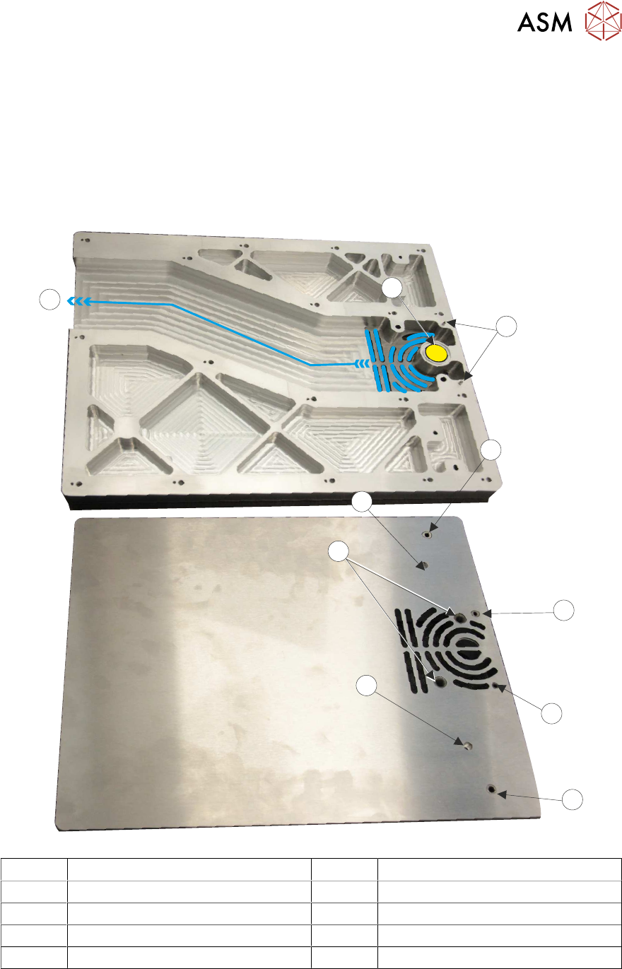
The tooling plate is fitted to the printer table and forms an interface with the product support tooling.
The tooling plate is constructed in two parts; the base (first image, viewed from underneath) and
the surface plate (second image), are bonded together,
The vacuum is pulled along a channel (10) in the base of the tooling table to the tooling table sur-
face plate.
1
2
3
4
5
6
7
8
9
10
2
1 Venturi Vacuum Port 6 4mm Plain Bush
2 Tooling Table Location Dowels 7 Hole for M4 x 40 Securing Screw
3 4mm Slotted Bush 8 6mm Plain Bush
4 3mm Slotted Bush 9 Hole for M4 x 40 Securing Screw
5 3mm Plain Bush 10 Vacuum Channel
Two dowel pins (2) on the tooling plate align with the holes on the printer table.
Once placed on the rising table the tooling plate is held in place with two M4 x 40 screws (7&9).
The remaining bushed holes correspond to those on the printer table and are used for tooling
placement.
5 TECHNICAL REFERENCE
5.1 SYSTEM OVERVIEW
16 STANDALONE MANUAL HIGH FLOW VACUUM (TQ) 12/2020
5.1.1.2 Diverter Valve
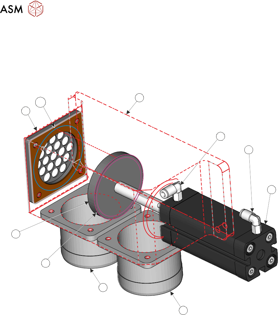
The diverter provides a means of rapidly venting the system vacuum whilst keeping the pump run-
ning. This action avoids the ramp-up needed to switch the pump back on when demanded.
The system software controls this action by activating the diverter valve.
Pneumatic supply to activate the valve is via a solenoid (1SOL4) located on the solenoid manifold.
A 60mm stroke, double acting cylinder (4), controls the diverter valve function - Flow or Vent. The
fittings on the body of the cylinder provide the air in (3) and air return (2).
1
5
6
7
10
9
8
2
3
4
In the graphic, item (1) depicts the diverter valve housing body as an outline.
In the High Flow Vacuum Off Whilst Printing mode, the table vacuum needs to diminish quickly.
Two solid state Reed switches (not shown) are located on the body of the diverter actuator (4), they
indicate the position of the actuator shaft (retracted or extended).
As the piston (8) retracts along its 60mm stroke it moves progressively away from the vent (9),
venting the system vacuum to atmosphere. It increasingly blanks the internal housing inlet port
shoulder (7).
The pump maintains its constant speed of 2900rpm during the print stroke in readiness for the
vacuum ON trigger.
At its fully extended stroke, the piston creates a face-to-face seal with the venting port (10).
Item (5) is the flange for the vacuum inlet from the pump and item (6) is the vacuum inlet flange to
the flow controller.
5 TECHNICAL REFERENCE
5.1 SYSTEM OVERVIEW
STANDALONE MANUAL HIGH FLOW VACUUM (TQ) 12/2020 17
5.1.1.3 Flow Controller
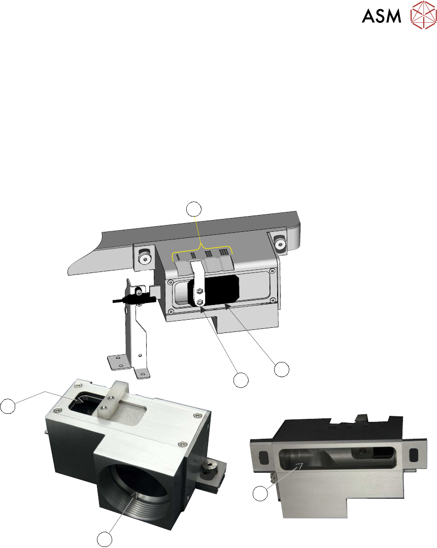
The support tooling is assembled into a box arrangement that creates a vacuum chamber to hold
the product during printing. The flow of air in the support tooling is fed through channels under the
tooling plate to the vacuum inlet port (3). The flow controller is a manually set device that controls
the evacuated air flow back to the pump via outlet (4).
By opening the control aperture (5), the vacuum flow in the support tooling decreases; closing the
aperture increases the flow. The sliding baffle plate (1) has a positive action when moved, the
handle (2) latches into a position as indicated (6).
The product size, through holes and aperture opening, affect the ability to hold the product during
printing and separation. By carrying out trials the user can determine the optimum set up for the
product; this increases the efficiency of the process.
2
6
1
3
5
4