03238396-01-01 High Flow Vacuum (TQ).pdf - 第19页
5 TECHNICAL REFERENCE 5.1 SYSTEM OVERVIEW STANDALONE MANUAL HIGH FLOW VACUUM (TQ) 12/2020 19 At the pump’s vacuum input port, a magnetic coupling (7) is used to connect to the diverter valve air hose. The pump and VPEC u…
5 TECHNICAL REFERENCE
5.1 SYSTEM OVERVIEW
18 STANDALONE MANUAL HIGH FLOW VACUUM (TQ) 12/2020
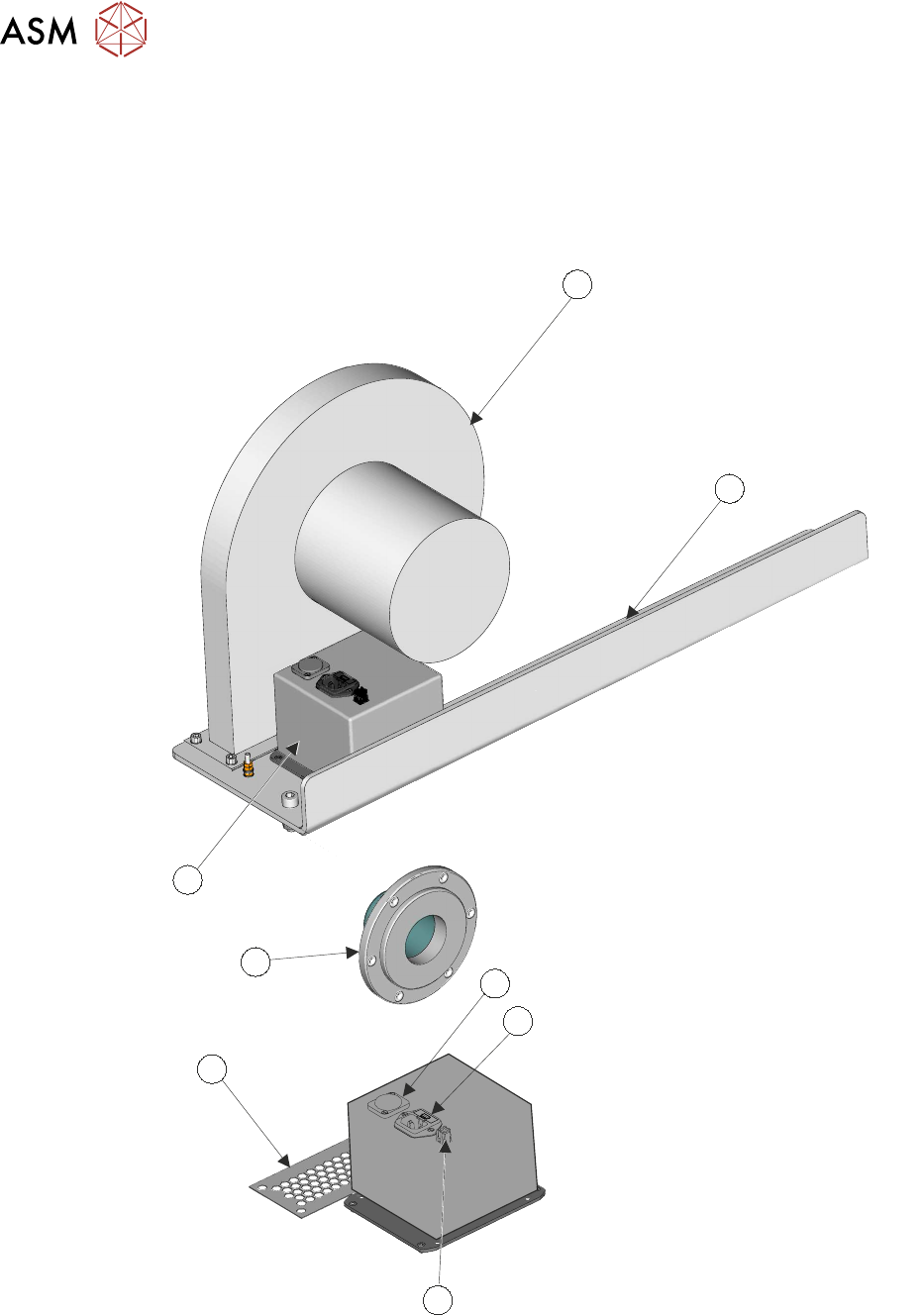
5.1.1.4 Pump Assembly
The assembly consists of the following:
●
Pump
●
Vac Pump Enable Controller (VPEC)
●
Mounting Plate and Beam
1
2
3
4
6
7
8
5
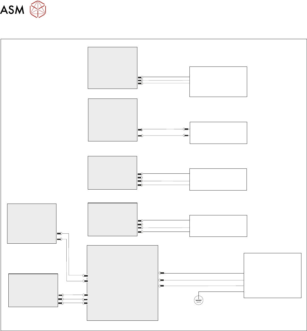
Refer to the electrical schematic.
Power to the pump (1) comes from the M71 power supply to the 5A fused input plug (4).
In the VPEC unit (8) an enable signal DOUT 7 from ESIO#3 latches CON 1 contactor relay. The
associated control switches close; this provides mains input to the pump via plug (3).
At the base of the pump, its output has a finger guard (6) to prevent access to the moving parts.

5 TECHNICAL REFERENCE
5.1 SYSTEM OVERVIEW
STANDALONE MANUAL HIGH FLOW VACUUM (TQ) 12/2020 19
At the pump’s vacuum input port, a magnetic coupling (7) is used to connect to the diverter valve
air hose.
The pump and VPEC unit are mounted onto the printer’s chassis with a mounting plate beam (2).
5.1.2 Operational Sequence
With High Flow Vacuum fitted and enabled, the print sequence is as follows:
1. Print is selected.
2. High Flow Vacuum is switched ON and remains on.
3. The product is loaded; the carrier/board moves into the print station and stops at the remote
board stop and is clamped.
4. The product is raised to vision height.
5. Camera sweep occurs to collect substrate and stencil fiducials data.
6. Align chase/stencil is performed.
7. The product is raised to print height.
8. The product is printed.
9. Separate the product from the stencil.
10. The product is lowered to vision height.
11. Camera sweep (post print alignment) is performed.
12. Table moves to transport height -unload product at transport height.
13. Carrier/board moves to outroad conveyor.
14. The sequence repeats from step 3 until the batch has printed.
15. High flow vacuum switches OFF.
5 TECHNICAL REFERENCE
5.2 ELECTRICAL SCHEMATIC
20 STANDALONE MANUAL HIGH FLOW VACUUM (TQ) 12/2020
5.2 ELECTRICAL SCHEMATIC
Breakout A
Part ESIO #1
Part ESIO #2
Part ESIO #2
Breakout A
Part ESIO #3
Part M71 PSU
Vac Pump Enable
Controller
BreakoutB
Part ESIO #1
1ASK13
2IO10
2IO11
5SK258
DIN 10
3APL27
Dout 7
M71PL34
8PL259
8PL260
DIN 09
1BSK25
PART
1SK6
+24V US
1BSK20
H F VAC
Present Sensor
1SE12
Table Present
Sensor
(Start Capacitor not shown)
Diverter Valve
Extended Sensor
2SE10
Diverter Valve
Retracted Sensor
2SE11
Tooling Vac Pump
HF VAC Diverter
Valve
1SOL4
L
N
E