03238396-01-01 High Flow Vacuum (TQ).pdf - 第32页
5 TECHNICAL REFERENCE 5.4 REPLACEMENT PROCEDURES 32 STANDALONE MANUAL HIGH FLOW VACUUM (TQ) 12/2020 9. Remove the right-hand safety cover. 1 10. Access ESIO-2 (1).
5 TECHNICAL REFERENCE
5.4 REPLACEMENT PROCEDURES
STANDALONE MANUAL HIGH FLOW VACUUM (TQ) 12/2020 31
To replace the diverter valve position sensors:
1
1. Turn the mains isolator switch to OFF and lockout the switch.
2. Remove the front panel.
3. Turn the Safety Lockout Switch, located on the Pneumatic Regulator, to the EXH position.
4. Fit a suitable locking device to the switch to prevent air being accidently applied.
5. Remove the vacuum pump and hoses as detailed previously in this section.
NOTE
Remove the hose ends only from the diverter valve hose connectors: items 1 and 4 in the
hose removal procedure above.
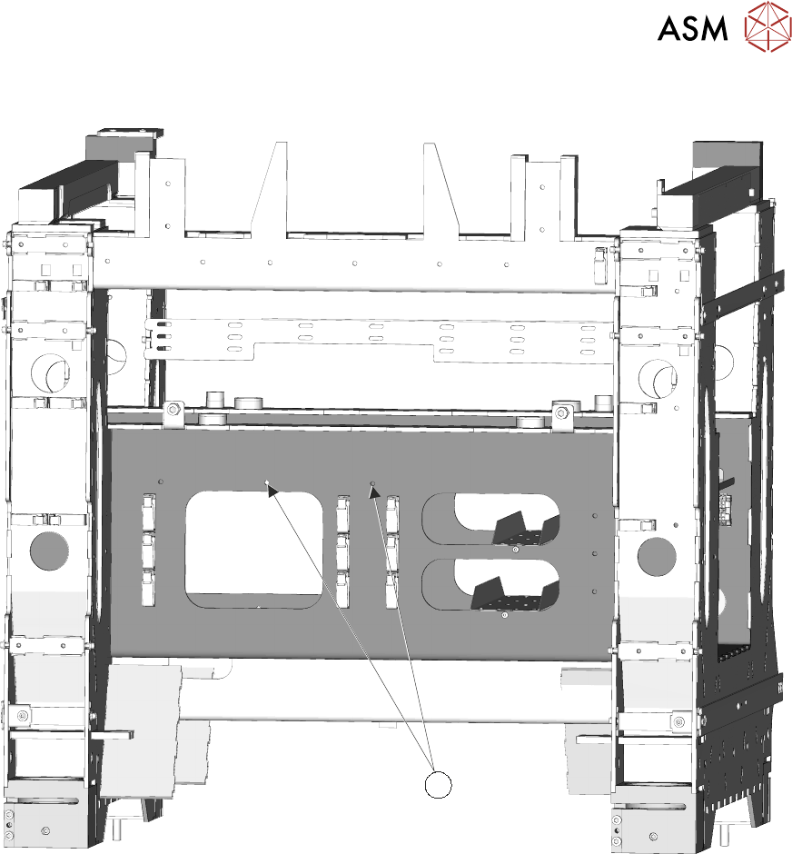
6. At the bulkhead locate the two M6 x 14 fixing screws (1).
7. Loosen the two screws, using a 5mm Allen key, whilst supporting the diverter valve (through
the access hole in the bulkhead panel).
8. Completely remove the screws and the diverter valve.
5 TECHNICAL REFERENCE
5.4 REPLACEMENT PROCEDURES
32 STANDALONE MANUAL HIGH FLOW VACUUM (TQ) 12/2020
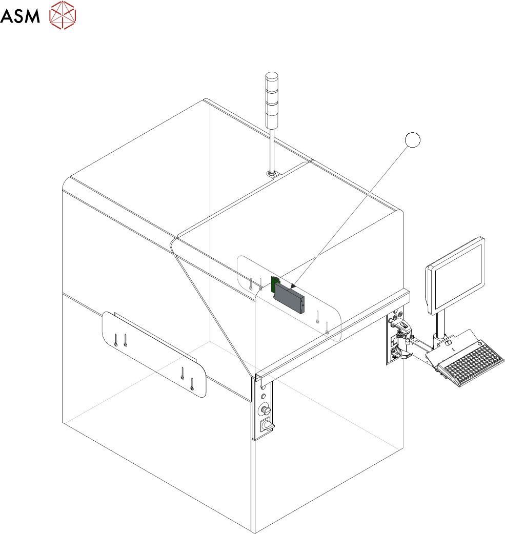
9. Remove the right-hand safety cover.
1
10. Access ESIO-2 (1).
5 TECHNICAL REFERENCE
5.4 REPLACEMENT PROCEDURES
STANDALONE MANUAL HIGH FLOW VACUUM (TQ) 12/2020 33
IO1 - IO8
IO9 - IO16
Extended
Retracted
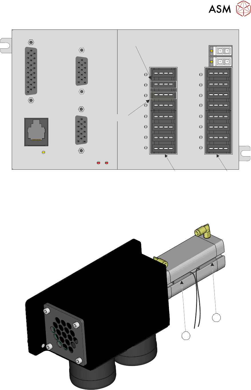
11. For the extended sensor remove socket I010, or for the retracted sensor remove socket I011.
12. Remove the fixings from the supports and remove the cable back to the diverter valve.
13. Mark the position of the sensor, to be replaced, in the actuator channel for future reference
(Diverter Valve Extended 2SE11 (1), Diverter Valve Retracted 2SE10(2)).
2
1
14. Using a flat-bladed watchmakers screwdriver remove the faulty sensor from the actuator slot.
15. Align the sensor to the mark scribed in step 13.
16. Secure the sensor with the screw using the flat-bladed watchmakers screwdriver.