SA_3214_en.pdf - 第16页
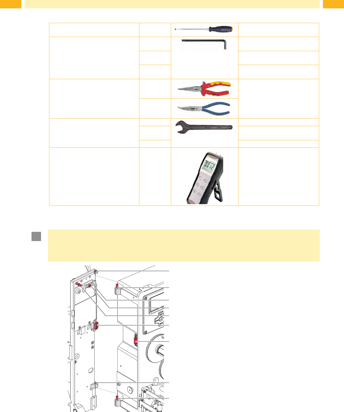
16 16 6.2 T ools Screwdriver with parallel blade 2.5 T o adjust the throttle valves and product sensor Hexagon key L-wrench 0.8 T o adjust the sensors (in contents of delivery) 2.5 For matched norm parts (in contents of …

15
6 Installation
6.1 Factory Defaults
i
Note!
Theapplicatorisbythefactoryadjustedafterdefaultvaluesinastandardconguration.Attitudesafter
thesevaluesguaranteeasmoothoperationwithsameconguration.
i
Note!
Incaseofacustomersetupwillbetheadjustmentswiththecustomizedconguration.
It's possible that the values are different to the standard values.
Then the values in the setup protocol are valid.
The standard settings are:
- Connecting on a cab Hermes+ printer, vertical
- Used Pad: cab part No.: 5963881 54x36
cab part No.: 5963878 54x36
- Used material for ex-factory settings: cab part No.: 5556472 54x35.5
- Pressure value of the compressed air 0.45 MPa (4.5 bar)
16 16
6.2 Tools
Screwdriver with parallel blade 2.5 To adjust the throttle valves and
product sensor
Hexagon key L-wrench 0.8
To adjust the sensors
(in contents of delivery)
2.5 For matched norm parts
(in contents of delivery)
4 Pad adjustments
Changing pad
Flat-round nose
straight
To mount/dismount tubes
angled
Open spanner SW 8 To change the throttle valves
SW 13 Setting the spring power on the
adapter bolt
SW20 Changing the cylinder
Manometer ± 7 bar
Air pressure control
Fig. 8 Tools
6.3 Mounting the applicator
!
Attention!
Disconnect the printer from the power supply before mounting the applicator!
Ensure a stable standing of the printer!
Connect the compressed air only after mounting the applicator to the printer!
1
1
2
2
6
7
3
4
5
1. Hang the applicator to the printer via the
female hinges (1) and the male hinges (2).
2. Connect SUB-D 15 male connector (6) to its
female counterpart (7).
3. To secure the applicator from slipping out of
hinges loosen screw (4) and move locking
plate (3) under the hinges. Tighten screw (4).
4. Swing the applicator to the printer and ensure
that the cable is not caught between the two.
5. Tighten the thumbscrew (5).
6. Raise the stopper from the transport position
to enable movement of cylinder Z.
Fig. 9 Mounting applicator to printer
6 Installation
17
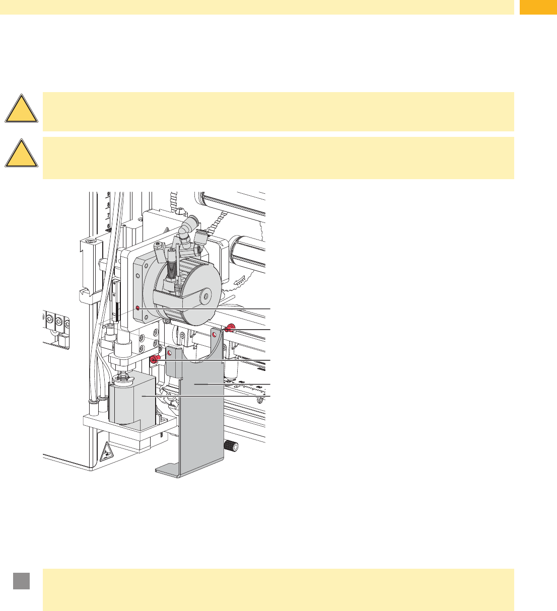
6.4 Transport lock
The transportation lock of the applicator prevents movement of the applicators parts to avoid damage and ensure
safe transportation for the applicator and the persons executing it.
!
Warning!
Ensure that the printer's power supply is disconnected and the compressed air supply is closed before
dismounting the applicator.
!
Warning!
Risk of injury and damage in the case of incorrect use and/or operation of the devices.
The applicator may only be used with a Hermes+ series printer.
2
3
2
1
4
Fig. 10 Transport lock
Remove the transport lock
1. Loosen screws (2) of the transport lock (3) .
2. Remove the transport lock (3).
!
Attention!
Mount the transportation lock for every transport.
Keep the transport lock and the screws.
Mounting the transport lock
1. Turn the swing arm (4) so that the pad holder is in the cut-out of the transport lock (3) .
This is an almost vertical position.
2. Place the transport lock (3) so that the holes in the transport lock (3) are over the holes (1) on both sides of the
swing cylinder socket.
3. Tighten screws (2).
6 Installation