SA_3214_en.pdf - 第21页
21 7.2 Adjusting the Swing Area of the Pad Theswingareaofthepadassemblyandthusthelabellingpositionaresettoclientspecicationsbythefactory .In case of changing the labelling position or the pad type i…
20 20
7 Adjustments
7.1 Pad Adjustments
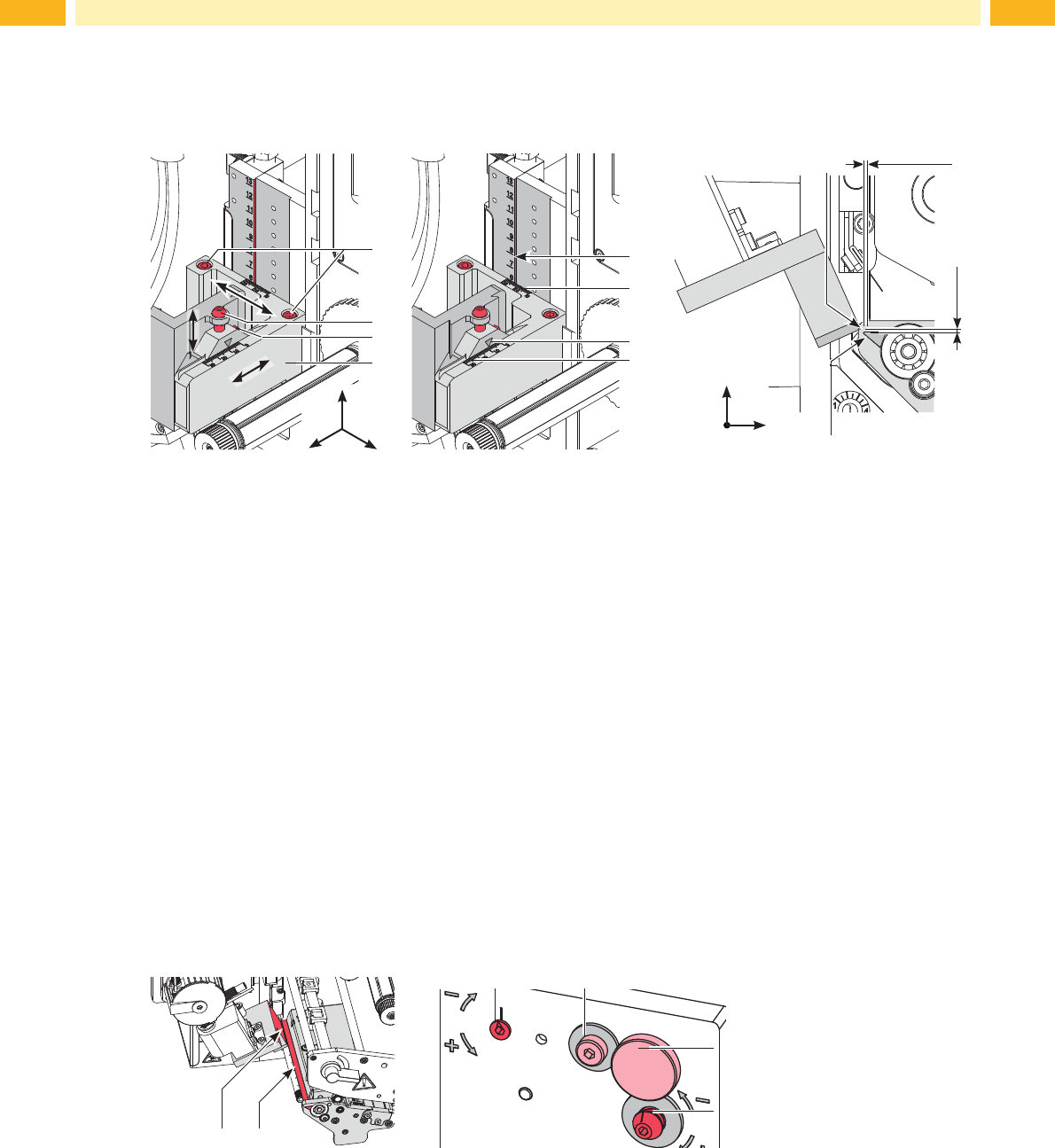
For optimal results it is necessary to place the pad precisely over the dispensed labels for the take over procedure.
Moving the pad in X-, Y- and Z-direction
10
1 mm
9
3
2
4
1
5
6
8
7
1 mm
y
x
z
x
y
z
Fig. 14 Moving the pad assembly
Adjustment in X-direction (sideways adjustment)
1. Loosen screw (3).
2. Move the cylinder assembly group (5) including pad along the cross beam until the pad is over the middle of the
label intended for application. For better orientation there is a graduation mark (7,8) depicted on the assembly
group.
3. Tighten screw (3).
Adjustment in Y-direction (print direction)
1. Loosen screw (1).
2. Move cylinder assembly (4) including pad along the guide rail so that the distance between the edge of the pad
(5) and the edge of the dispense plate (6) of the printer is approximately 1 mm. Graduation (5,6) can be used for
orientation.
3. Tighten screws (1).
Adjustment in Z-direction (height adjustment)
1. Loosen screw (3).
2. Turn setting screw (2) so that the bottom of the pad is 1 mm over the top edge of the dispense plate (6).
3. Tighten screw (3).
Adjusting the Parallelism between Pad and Dispense Edge
The edge of the pad must be parallel to the dispense edge of the printer.
9 10
14
13
11 12
Fig. 15 Adjusting the pad to the dispense edge
1. Loosen knurled screw (13) and screw (12).
2. Push the applicator against the printer and adjust the angle between applicator pad edge (9) and printer
dispensing plate (10) via the setting screw (14) and the eccentric (11).
3. Tightenscrew(12)andrextheapplicatorviaknurledscrew(13)oftheprinter.
21
7.2 Adjusting the Swing Area of the Pad
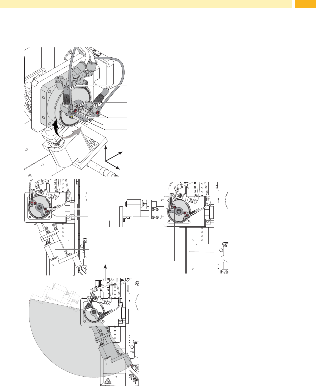
Theswingareaofthepadassemblyandthusthelabellingpositionaresettoclientspecicationsbythefactory.In
case of changing the labelling position or the pad type is may be necessary to adjust the swing area (angle).
2
3
y
x
z
4
1
5
• Loosen screw (2).
• Turn the lever (6) with the stopper (3) in the desired
labelling position.
• Turn stopper with the sensor (1/4) so that the spring is
pushed in entirely.
• Tighten screw (2) .
• Loosen screw (3) and move the sensor (4) so that the
LED will lights up.
• Tighten screw (3) .
• Loosen nut of the stopper (1). Fine tune the setup by
turning the stopper (1) and tighten the nut to lock the
system in place.
• If necessary readjust sensor (4).
2
3
6
236
ca. 140°
Fig. 16 Adjusting the swing area of the pad
y
x
z
7 Adjustments
22 22
7.3 Stopper for Operation Mode "Blow on"
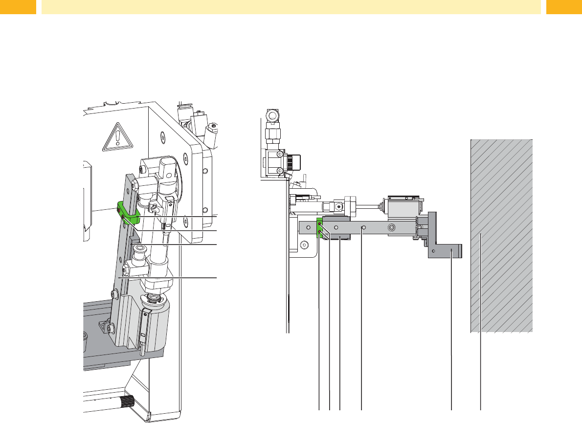
In order to label a product without physically coming into contact with it use the "blow on" mode. The stopper (1) will
limit the downward movement of the cylinder and prevent contact with the product.
1
1
3
2
2 5 64
4
3
Fig. 17 Adjust the stopper in the operation mode "blow"
1. Turn off the air pressure.
2. Remove the tubes from the throttle valves of the swing-, extension- and lift- cylinder.
3. Loosen the screws (2) on the stopper (1).
4. Place the product (6) in the position it is to be labeled in.
5. Swing the pivot arm to the stopper manully. This pivot cylinder is adjusted according to 4.1.5.
6. Pull the pad assembly (5) toward the product until the distance between pad (5) and the product (6) is a maximum
of 10 mm apart.
7. Move the stopper (1) along the rail (4) to the carriage (3) and tighten screws (2).
8. Reconnect the tubes into the throttle valves and pivot out the swing cylinder as well as the lift cylinder again.
7 Adjustments