SA_3214_en.pdf - 第33页
33 10 Spare Parts 10.1 Retainer Assembly Fig. 29 Retainer Assembly - Spare Part No. Part-No. Description PU Serial No. from to 1 5902489.001 Screw DIN7984-M4x8 10 2 5964129.001 Cover 1 3 5964367.001 Knurled Screw 1 4 596…
32 32
9 Operation
9.1 Test Mode without Print Job
!
Warning!
The pad will be moved to the starting position immediately!
Dangerofinjurytohandsandngersbythemovingpad!
Do not reach into the zone of the moving pad and keep long hair, loose clothes, and jewelry away.
2
1
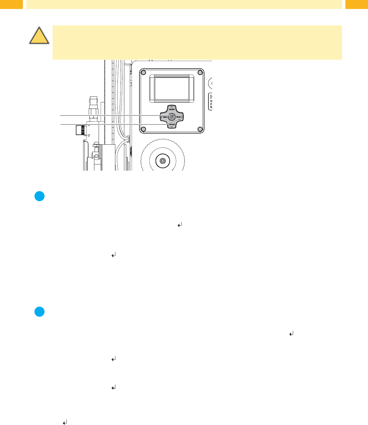
Fig. 28 Test mode via Enter key
i
Note!
Pleaseusethetestmodetoadjusttheparameter"Peelposition"intheprinterconguration.
The whole labelling process can be simulated without the need for a print job, or a connection to a computer, by alter-
nately pressing the feed (2) key and the Enter key
(1):
Press the feed key (2).
A blank label is fed. The vacuum of the pad as well as the supporting air (blow tube) are switched on. After the
label has been picked up by the pad, the supporting air is switched off.
Press the Enter key (1).
The pad is moved to the labelling position. A sensor signals when the labelling position is reached. The vacuum is
switched off and the label is placed onto the product. Then the pad is moved back into the starting position.
9.2 Test Mode with Print Job
i
Note!
Please use the test mode to adjust the peel-off offset in the software.
This method allows the checking of the labelling process with real print data using the Enter key
(1).
Send a print job.
The test mode is executed in two half cycles:
Press the Enter key (1).
Half cycle 1
A label is printed. The vacuum of the pad as well as the supporting air (blow tube) are switched on. After the label
has been picked up by the pad the supporting air is switched off.
Press the Enter key (1) again.
Half cycle 2
The pad is moved to the labelling position. A sensor signals when the labelling position is reached. The vacuum is
switched off and the label is placed onto the product. Then the pad is moved back into the starting position.
Ifthelabelismanuallyremovedfromthepadafterthersthalfcycle,thehalfcycle1willberepeatedwhentheEnter
key key is pressed again.
33
10 Spare Parts
10.1 Retainer Assembly
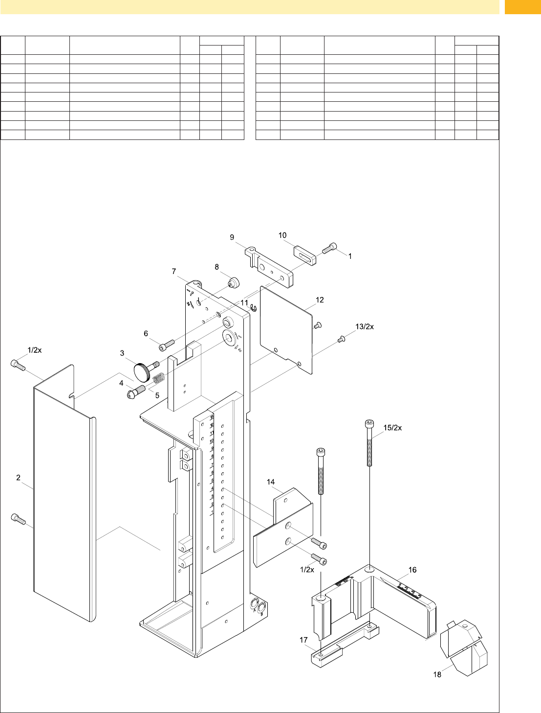
Fig. 29 Retainer Assembly - Spare Part
No. Part-No. Description PU Serial No.
from to
1 5902489.001 Screw DIN7984-M4x8 10
2 5964129.001 Cover 1
3 5964367.001 Knurled Screw 1
4 5965963.001 Set Screw 1
5 5904544.001 Spring 10
6 5902241.001 Screw DIN7984-M4x10 10
7 5964036.001 Base Plate 1
8 5966530.001 Eccentric 1
9 5966529.001 Hinges 1
No. Part-No. Description PU Serial No.
from to
10 5964090.001 Bar 1
11 5903525.001 E-Ring DIN6799-4 10
12 5964429.001 Plate 1
13 5902021.001 Screw DIN7991-M3x6 10
14 5970013.001
AdapterProle 1
15 5902167.001 Screw DIN912 M5x50 10
16 5964331.001 Crossbeam 1
17 5964328.001 Clamping Element 1
18 5964062.001 Binder 1
34 34
23: * Option
10 Spare Parts
10.2 Pneumatics Retainer Assembly
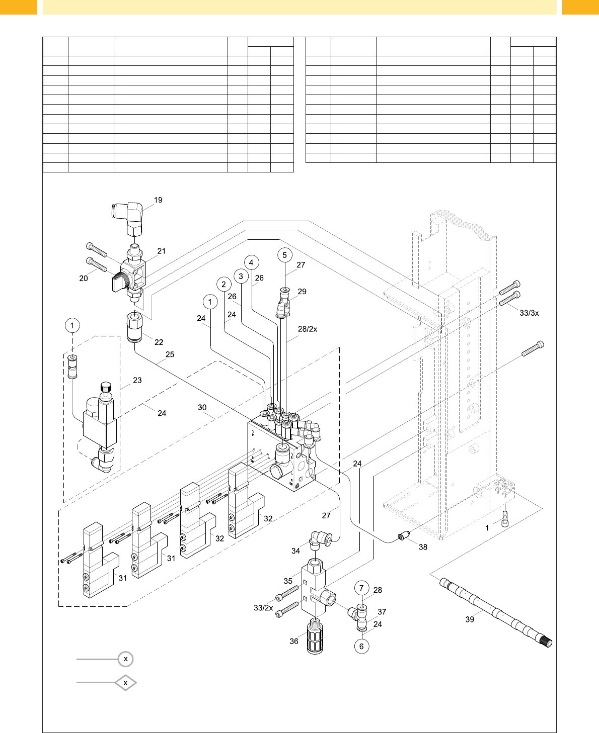
Fig. 30 Pneumatics Retainer Assembly - Spare Part
No. Part-No. Description PU Serial No.
from to
1 5902489.001 Screw DIN7984-M4x8 10
19 5905285.001 Push-in L-Connector 1
20 5902863.001 Screw DIN7984 M4x25 10
21 5905284.001 Block Valve 1
22 5906656.001 Push-in/threaded Fitting 1
23 5966414.001 Pressure Reduce Valve 1
24 5966460.001 Tube 2m
25 5966465.001 Tube 2m
26 5966466.001 Tube 2m
27 5966464.001 Tube 2m
28 5966463.001 Tube 2m
29 5905972.001 Push-in Y-Fitting 1
No. Part-No. Description PU Serial No.
from to
30 5906852.001 Valve Block 1
31 5906021.001 Valve 1
32 5906022.001 Valve 1
33 5902863.001 Screw DIN7984 M4x25 10
34 5905317.001 Push-in L-Connector 1
35 5906844.001 Vacuum Generator 1
36 5905257.001 Silencer 1
37 5905338.001 Push-in T-Connector 1
38 5905283.001 Push-in/threaded Fitting 1
39.1 5964277.001 Blow Tube 2" 1
39.2 5964095.001 Blow Tube 4" 1
Cable
Tube