SA_3214_en.pdf - 第28页
28 28 7 Adjustments Measuring Point Support Air (MP S) 3 2 1 RP S Use a manometer with a measuring range of -7 to 7 bar . MP S: Support Air (default value 2 bar) 1. Remove cover and connect the manometer to the MP S. - T…
27
7 Adjustments
7.10 Blow Tube (Support Air) Adjustments
For an optimal take up of the label by the applicator set the supporting air so that the entire label is constantly, without
turbulence, blown onto the pad.
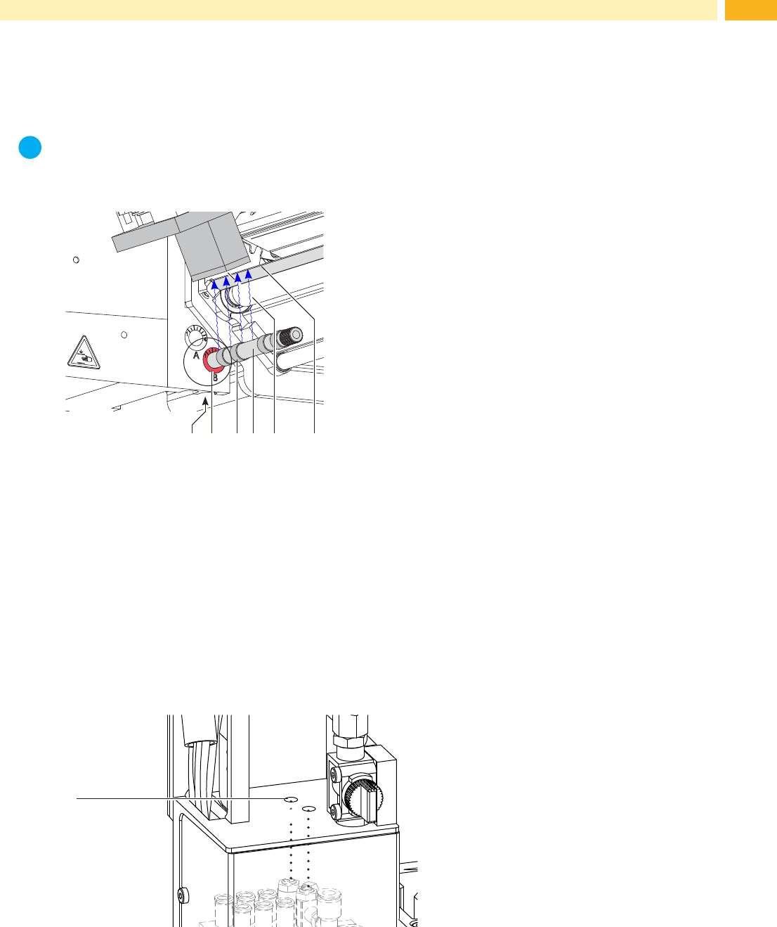
All holes in the blow tube that exceed the width of the label should be covered by a rubber ring (3).
The factory default air pressure of the blow tube is 2 bar.
i
Note!
If the breadth of the printer is changed (2", 4" or 6") the appropriate blow tube should be used. When
changingthelabelwidthcheckthenumberofcoveredholesoftheblowtubeandreconguretheblowtube
settings.
1
2 3
5
6
4
Fig. 25 Adjust the blow tube
The blow tube (4) for the supporting air can be rotated around its axis. That way the direction of the supporting air can
be optimized.
1. Loosen screw (1).
2. Place the blow tube (4) into the tube adapter B (2).
Turn the blow tube (2) in the direction that supports the uptake of the label from the dispensing edge (6) to the
pad (5).
Turn the blow tube (2) in that direction, that the air current supports the sucking of the label from the dispense
edge (6) by the pad (5).
• For smaller labels direct the air current to the dispense edge (5) of the printer.
• For larger labels direct the air current away from the dispense edge (6) .
Use the graduation for orientation.
3. Tighten screw (1).
support air
vacuum
1
Fig. 26 Throttle valve "support air"
The throttle valve (1) enables the variation of the supporting air for optimizing the label take up procedure.
To increase the strength of the supporting air turn the screw of the valve (1) counterclockwise.
28 28
7 Adjustments
Measuring Point Support Air (MP S)
3
2
1
RP S
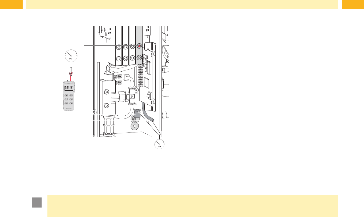
Use a manometer with a measuring range of -7 to 7 bar.
MP S: Support Air (default value 2 bar)
1. Remove cover and connect the manometer to the MP S.
- Tube (3) from valve block to blow tube connector.
- Fitting (2) on the blow tube.
2. While the compressed air is connected, push the micro
switch (1) to measure the pressure.
3. Adjust the strength of the "support air" via the corre-
sponding throttle valve.
4. Remount the cover.
Fig. 27 Measuring points for support air.
!
Attention!
After pressure measurements have concluded reconnect and recheck all the tubes.
29
8 Conguration
The tamp applicator can be operated in different ways. While the original process stays the same, the operation
mode can be chosen from within the printer setup.
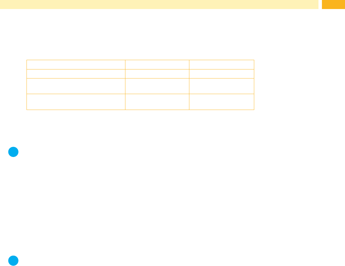
The most important setting is the selection between the operation modes "Stamp on" and "Blow on".
Additionally the applicator has different application modes concerning the order of printing and applying within one
labelling cycle
Stamp on Blow on
Print/Apply x x
Apply/Print
Waiting position up
x x
Apply/Print
Waiting position down
- x
Table 3 Operation and application modes
Additionally all operating modes can be adjusted by setting different time delays.
i
Note!
Formoreinformationabouttheprintercongurationandthefunctionofthekeysinthenavigatorpad
Congurationmanualoftheprinter/ Operator's manual of the printer
8.1 Method for Changing the Printer Setup
1. Press the menu key.
2. Select Setup > Machine param. > Applicator.
3. Select and adjust the needed parameters.
4. Return to the "Ready" mode.
8.2 Quick Mode for Setting the Delay Times
Besidethestandardmethodfortheprintercongurationthereisaquickmodetoadjusttheavailabledelaytimes.
i
Note!
The quick mode settings can be made during operation . The changes affect directly the current print job.
1. Press and hold the menu key for at least 2 seconds.
Therstdelaytimeappearsonthedisplay.
2. Adjust the delay time by pressing the ~ key or key.
3. To switch between the different delay times press the } key.
4. To leave the quick setup mode press the | key.
The selected delay times are saved.