SA_3214_en.pdf - 第6页
6 6 2 Product Description 2.1 Important Features • The supporting air and the vacuum as well as the speed of the cylinder are adjustable. That way the applicator can be adapted to different label materials and sizes. • T…
5
1 Introduction
• Before mounting the delivered components disconnect the printer from the power supply and close the shutoff
valve of the applicator.
• Only connect the device to other devices which have a protective low voltage.
• Switch off all affected devices (computer, printer, accessories) before connecting or disconnecting.
• In operation, moving parts are easily accessible.
This applies especially for the zone, where the pad is moved between the starting and the labelling position.
During operation do not reach into that zone and keep long hair, loose clothes, and jewelry distant. Before any
manipulations in those areas, close the shutoff valve.
• The device may only be used in a dry environment, do not expose it to moisture (sprays of water, mists, etc.).
• Do not use the device in an explosive atmosphere.
• Do not use the device close to high-voltage power lines.
• Perform only those actions described in this operating manual.
Work going beyond this may only be performed by trained personnel or service technicians.
• Unauthorized interference with electronic modules or their software can cause malfunctions.
• Otherunauthorizedworkonormodicationstothedevicecanalsoendangeroperationalsafety.
• Alwayshaveserviceworkdoneinaqualiedworkshop,wherethepersonnelhavethetechnicalknowledgeand
tools required to do the necessary work.
• There are various warning stickers on the device. They draw your attention to dangers. Warning stickers must
therefore not be removed, as then you and other people cannot be aware of dangers and may be injured.
1.4 Safety Markings
3
1
2
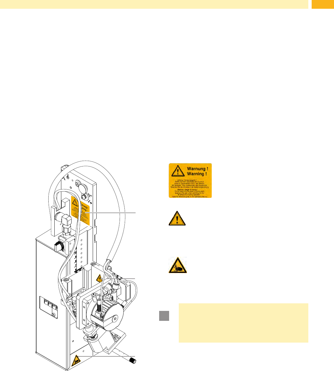
1: Warning potential injury by
moving parts!
2:
Cylinder is under pressure, also
after it is switched off!
3:
Danger of crushing hands and/or
ngersbythemovingpad!
!
Attention!
Never remove or cover safety markings!
Replace it in case of damage!
Fig. 1 Safety marking
1.5 Environment
Obsolete devices contain valuable recyclable materials that should be sent for recycling.
Send to suitable collection points, separately from residual waste.
The modular construction of the applicator enables it to be easily disassembled into its component parts.
Send the parts for recycling.
6 6
2 Product Description
2.1 Important Features
• The supporting air and the vacuum as well as the speed of the cylinder are adjustable. That way the applicator
can be adapted to different label materials and sizes.
• To avoid contamination within the vacuum channels they are cleaned by air pressure impulse at the end of each
application.
• For operation in a system the I/O interface of the printer can be used.
2.2 Technical Data
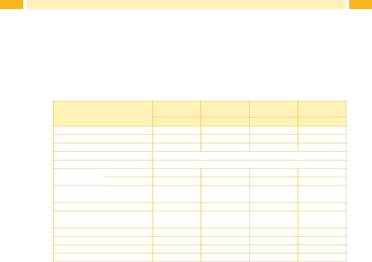
Label transfer method Tamp pad Tamp pad
with foam
Tamp pad
with label stop
Blow pad
3214 L/R 11 F 3214 L/R 12 F 3214 L/R 61 F 3214 L/R 2100
Label width in mm for Hermes
+
4 4 -58 10 - 58 10 - 58 10 - 58
for Hermes
+
6 10 - 114 10 - 114 10 - 114 10 - 80
Label height in mm 5 - 80 10 - 80 5 - 80 10 - 80
Compressed air pressure 0.45 MPa (4.5 bar)
Sound pressure level under 74 dB(A)
Product during
labeling
xed
¢ ¢ ¢ ¢
in motion - - -
¢
Labeling onto the
product
sideways
¢ ¢ ¢ ¢
Product height x
¢ ¢ ¢ ¢
Distance of product to
dispensing edge in mm
250 - 280 250 - 280 250 - 280 250 - 280
Horizontal short stroke cylinder in mm 5 - 30 5 - 30 5 - 30 5 - 30
Swing angle 45° - 95° 45° - 95° 45° - 95° 45° - 95°
Immersion depth pad F
2)
up to mm 30 30 30 -
Cycle time about frequency/min.
1)
25 25 25 25
1)
Determined at 100 mm stroke below device / smallest label height / print speed 100 mm/s .
2)
Immersion depth at applicator >25 mm, the cover of the Hermes
+
mustbemodied.
Table 1 Technical Data
7
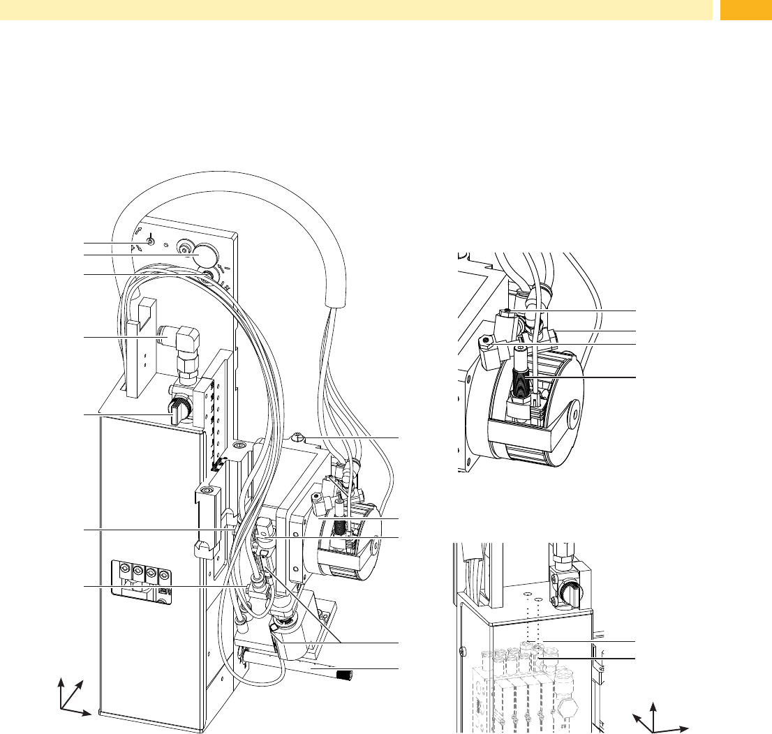
2.3 Overview
support air
vacuum
17
18
12
11
7
6
5
4
2
8
10
3
1
9
13
14
15
16
Fig. 2 Device overview - front view
1 Eccentric o adjust the angle between applicator and
printer
2 Knurled screw for attaching the applicator to the
printer
3 Setting screw to adjust the angle between applicator
and printer
4 Compressed air connector
5 Shutoff valve
6 Throttle valve cylinder - move in Z-direction
7 Throttle valve cylinder - move out Z-direction
8 Setting screw for vertical adjustment cylinder
assembly
9 Swing drive
10 Cylinder - Z-direction
11 Sensor labeling position
12 Blow tube for supporting air
13 Throttle valve swing drive - swing in
14 Throttle valve swing drive - swing in
15 Throttle valve swing drive - swing out
16 Setting screw to adjust the angle of the swing area
17 Support air throttle valve
18 Vacuum throttle valve
Front view
Throttle valves vacuum/support air
y
x
z
2 Product Description
Swing drive
y
x
z